Clamping groove assembling type steel pipe column and steel beam connecting joint and construction method thereof

A technology for connecting nodes and construction methods, which is applied in the direction of architecture and building construction, and can solve problems such as complex construction, deformation or damage of steel pipe walls, etc., and achieve the effect of fast construction on site and high degree of industrialization

Active Publication Date: 2016-02-24
HANGZHOU TONGMSK DESIGN CO LTD
View PDF6 Cites 14 Cited by
  • Summary
  • Abstract
  • Description
  • Claims
  • Application Information

AI Technical Summary

Problems solved by technology

[0004] The purpose of the present invention is to solve the problems such as the complex on-site construction of the traditional steel column and steel beam connection node, the deformation or damage of the steel pipe wall during the construction process, etc., and pr

Method used


Image

  • Clamping groove assembling type steel pipe column and steel beam connecting joint and construction method thereof
  • Clamping groove assembling type steel pipe column and steel beam connecting joint and construction method thereof
  • Clamping groove assembling type steel pipe column and steel beam connecting joint and construction method thereof

Examples


Embodiment 1

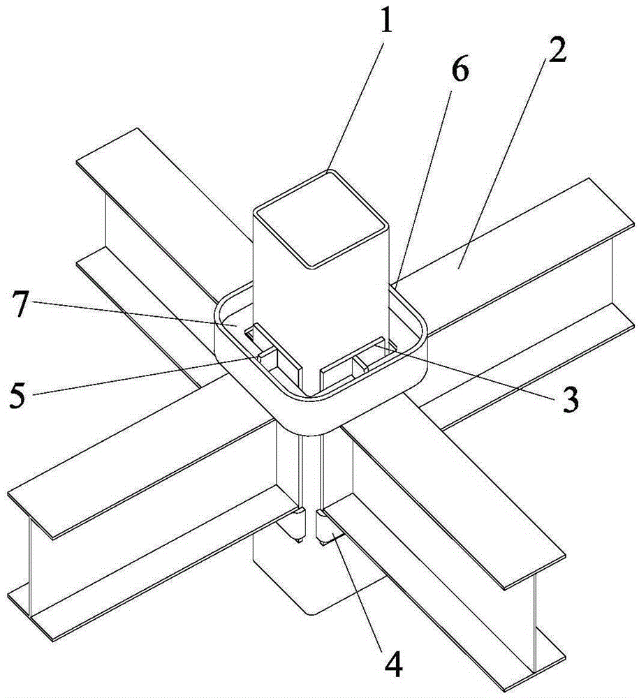
[0041] Such as Figure 5 ~ Figure 7 As shown, the nodes include steel pipe columns 1, H-shaped steel beams 2, U-shaped slots 4 and movable steel hoops 6; as Figure 7 As shown, a plurality of H-shaped steel beams 2 are horizontally connected to the side walls around the steel pipe column 1, the ends of the H-shaped steel beams 2 are fixedly welded with steel beam end plates 3 extending along the beam height direction of the steel pipe column 1, and the lower side of the steel pipe column 1 is welded There is a U-shaped card slot 4, the lower side of the steel beam end plate 3 is inserted into the U-shaped card slot 4, the upper side of the steel pipe column 1 is equipped with a ring-shaped movable steel hoop 6, and the upper end of the surrounding steel beam end plate 3 adopts a movable steel hoop 6 Tighten the connection.

[0042] Such as Figure 5 As shown, the steel pipe column 1 is a square column, U-shaped slots 4 are welded on the underside of the four side walls, and ...

Embodiment 2

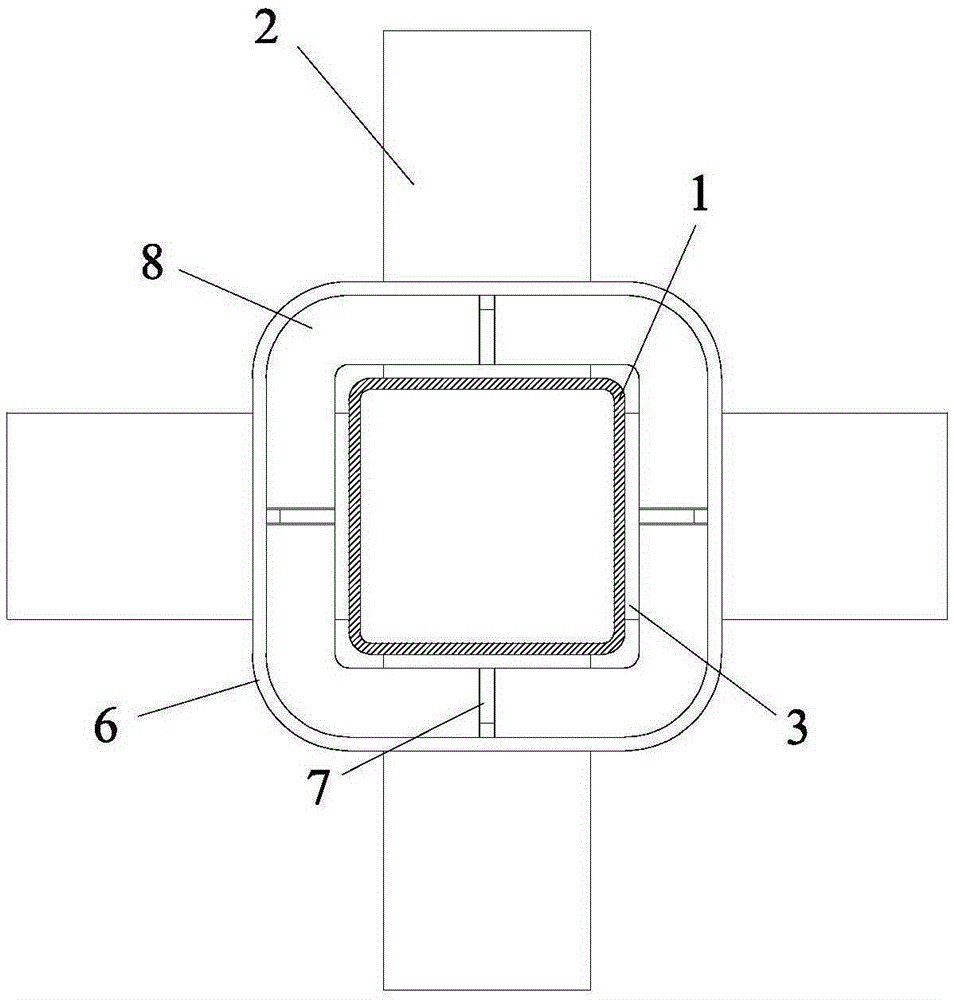
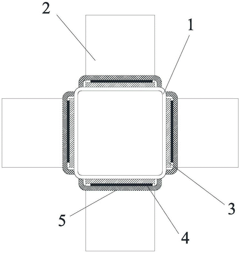
[0050] Such as Figure 1 to Figure 4 As shown, the nodes include steel pipe columns 1, H-shaped steel beams 2, U-shaped slots 4 and movable steel hoops 6; as Figure 4 As shown, a plurality of H-shaped steel beams 2 are horizontally connected to the side walls around the steel pipe column 1, the ends of the H-shaped steel beams 2 are fixedly welded with steel beam end plates 3 extending along the beam height direction of the steel pipe column 1, and the lower side of the steel pipe column 1 is welded There is a U-shaped slot 4, the lower side of the steel beam end plate 3 is inserted into the U-shaped slot 4, and the upper side of the steel pipe column 1 is equipped with an annular movable steel hoop 6. The steel pipe column 1 is a square column, and the lower sides of the four side walls are welded with U-shaped slots 4, and the upper ends of the steel beam end plates 3 of the four side walls are tightly connected by stiffening plates and movable steel hoops 6.

[0051] The ...


PUM


Abstract

The invention discloses a clamping groove assembling type steel pipe column and steel beam connecting joint and a construction method thereof. A plurality of H-shaped steel beams are horizontally connected to the side wall of the periphery of a steel pipe column. A steel beam end plate extending in the beam height direction of the steel pipe column is fixedly welded to the end face of each H-shaped steel beam. A U-shaped clamping groove is welded to the lower side of the steel pipe column. The lower sides of the steel beam end plates are inserted into the U-shaped clamping groove. An annular movable steel hoop is installed on the upper side of the steel pipe column. The upper ends of the steel beam end plates are hooped and connected through the movable steel hoop or hooped and connected in the mode that a reinforcing plate is matched with the movable steel hoop. Insertion plates for fastening are inserted into gaps between the U-shaped clamping groove and the steel beam end plates. An annular reinforcing plate is welded to the portion, matched with the movable steel hoop, of the middle of the inner wall of the reinforcing plate. An end plate reinforcing plate is fixedly arranged at the joint of an upper wing edge and the middle of the upper end of each steel beam end plate. A notch is formed in the middle of the annular reinforcing plate on each side. The clamping groove assembling type steel pipe column and steel beam connecting joint has the advantages that the industrial degree is high, no welding or bolt connection is needed on a construction site, and the construction speed is high, and has better technical benefits.

Description

technical field [0001] The invention relates to a steel node and a construction method, in particular to a groove-assembled steel pipe column and steel beam connection node and a construction method thereof, which can be widely used in steel structure workshops, houses, apartments and other buildings. Background technique [0002] The report of the 18th National Congress of the Communist Party of China proposed to vigorously promote the construction of ecological civilization; in January 2013, the General Office of the State Council forwarded the "Green Building Action Plan" of the Development and Reform Commission and the Ministry of Housing and Urban-Rural Development; Document No. 41 of the State Council [2013] required to resolve production capacity The serious surplus requires the promotion of steel utilization in the construction field, and the industrialization of construction, especially the industrialization of steel structure buildings, is imperative. The steel str...

Claims


Application Information

Patent Timeline
IPC IPC(8): E04B1/58
CPCE04B1/5818E04B2001/5875E04B2001/5887
Inventor 徐永斌
Owner HANGZHOU TONGMSK DESIGN CO LTD
Why Eureka
Try Eureka