
Cable tray

A cable tray and C-shaped steel technology, applied in electrical components and other directions, can solve the problems of laborious assembly and installation of workers, self-heavy steel, damage to support parts, etc., and achieve the effect of convenient and fast assembly process, weight reduction, and easy disassembly.

Inactive Publication Date: 2016-02-24
江苏安荣电气设备有限公司
View PDF2 Cites 3 Cited by
  • Summary
  • Abstract
  • Description
  • Claims
  • Application Information

AI Technical Summary

Problems solved by technology

[0002] Cable trays are generally suitable for large enterprises, large-scale engineering transformation, cable erection, large bridges, subway cable laying and offshore drilling; cable trays for these occasions are generally There are basic rigidity requirements, so most of the common cable bridges are made of steel, but the weight of the steel is relatively large, which makes it very difficult for workers to assemble and install, which reduces work efficiency; at the same time, the heavy weight is not easy to disassemble and maintain. It is also easy to cause premature damage to the support

Method used


Image

  • Cable tray
  • Cable tray
  • Cable tray

Examples


specific Embodiment approach

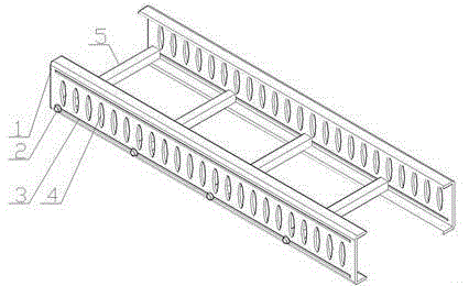
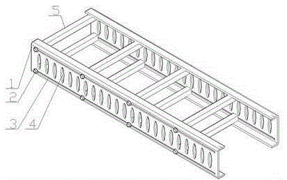
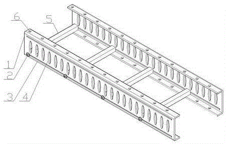
[0024] Figure 1 to Figure 5 A specific embodiment of the invention is shown in which figure 1 , figure 2 and image 3 It is three kinds of embodiments, and its basic structure is identical, figure 2 Compared with Embodiment 1, the shown Embodiment 2 only has more upper-layer connectors; image 3 Compared with embodiment 1, the illustrated embodiment 3 is only provided with a plurality of spare holes 6 on the horizontal extension wall of the C-shaped steel;

[0025] Such as figure 1 As shown, the present invention comprises two C-shaped steel 1s with opposite openings. The C-shaped steel 1 includes vertical side walls and two horizontal extension walls at the upper and lower ends of the side walls; The connecting groove 3, the side wall of the C-shaped steel 1 is provided with a plurality of weight-reducing holes 4 at intervals along the height direction of the C-shaped steel;

[0026] The present invention also includes a plurality of connectors for connecting two C-s...


PUM


Abstract

The invention discloses a cable tray which is lighter in weight, convenient and simple to assemble and high in construction efficiency. The cable tray comprises two pieces of C steel with openings arranged oppositely as well as a plurality of connecting elements used for connecting the two pieces of C steel, wherein each C steel comprises a vertical side wall and two horizontal extending walls arranged at upper and lower ends of the side wall, a connecting groove is formed in the side wall of the C steel in the length direction of the C steel, and a plurality of weight reducing holes are formed at intervals in the side wall of the C steel in the height direction of the C steel; the plurality of connecting elements are arranged in the length direction of the C steel, each connecting element comprises a hollow connecting steel tube arranged between the two pieces of C steel, connecting blocks are manufactured at two ends of the inside of the connecting steel tube, and a through hole is formed in each connecting block in the length direction of the connecting steel tube; each connecting element further comprises a fastener which penetrates through the through holes of the connecting blocks and the corresponding connecting groove for fastening connection of the corresponding connecting steel tube and the corresponding C steel.

Description

technical field [0001] The invention relates to the field of cable installation components, in particular to a cable tray. Background technique [0002] Cable trays are generally suitable for large enterprises, large-scale engineering transformation, cable erection, large bridges, subway cable laying and marine drilling fields; cable trays in these occasions generally have basic rigidity requirements, so common cable trays are mostly steel. However, the heavy weight of steel makes it very difficult for workers to assemble and install, which reduces work efficiency; at the same time, the heavy weight is not easy to disassemble and maintain, and it is easy to cause premature damage to the support. Contents of the invention [0003] The technical problem to be solved by the present invention is to provide a cable tray with light weight, convenient and simple assembly and high construction efficiency in view of the deficiencies in the above-mentioned prior art. [0004] The t...

Claims


Application Information

Patent Timeline
IPC IPC(8): H02G3/04
CPCH02G3/045
Inventor 张春雨
Owner 江苏安荣电气设备有限公司
Features
  • Generate Ideas
  • Intellectual Property
  • Life Sciences
  • Materials
  • Tech Scout
  • Unparalleled Data Quality
  • Higher Quality Content
  • 60% Fewer Hallucinations
Learn More