Electric switch installation assembly

A technology for electrical switches and installation components, applied in electrical components, electrical equipment structural parts, electrical equipment shells/cabinets/drawers, etc., can solve the problems of heat dissipation or cooling in difficult distribution cabinets, and achieve reliable operation and simple structure. , Effective cooling effect

Inactive Publication Date: 2016-02-24
范全有
View PDF4 Cites 0 Cited by
  • Summary
  • Abstract
  • Description
  • Claims
  • Application Information

AI Technical Summary

Problems solved by technology

Conventional cooling methods often use exhaust fans and dedicated cooling fans, etc., but it is difficult to dissipate

Method used


Image

  • Electric switch installation assembly
  • Electric switch installation assembly
  • Electric switch installation assembly

Examples


Embodiment Construction

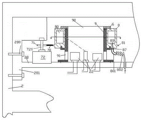
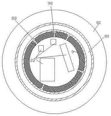
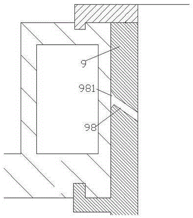
[0009] pass below Figure 1-3 The present invention will be described in detail.

[0010] According to an embodiment, an electrical switch installation assembly includes a mounting plate 28 that can be fixed on the side wall of the cabinet body 2 of the power distribution cabinet through a fastener 280 and is used for installing an electrical switch for power distribution, installed on the The electrical switch 22 that needs to be cooled on the mounting plate 28, and the cooling device that cools the electrical switch that needs to be cooled, the cooling device includes fixedly installed on the mounting plate 28, surrounding the need Cooled electrical switch and a fixed bearing cylinder 9 with a ventilation opening 91 at the bottom, the outer peripheral wall of the fixed bearing cylinder 9 is rotatably fitted with an air distribution ring 8 with an annular cavity 80, wherein, The top end of the fixed bearing cylinder 9 is fixedly provided with a detachable stop ring 6 to rota...


PUM


Abstract

An electric switch installation assembly comprises an installation plate (28) which is fixed on a side wall of a cabinet body (2) of a power distribution cabinet through fastening members (280) and is used for installing electric switches used for power distribution, the electric switches (22) installed on the installation plate (28) and needing to be cooled, and a cooling device used for cooling the electric switches needing to be cooled. The cooling device comprises a fixed bearing cylinder (9), wherein the fixed bearing cylinder is fixedly installed on the installation plate (28) and surrounds the electric switches needing to be cooled, and the bottom part of the fixed bearing cylinder is provided with ventilation openings (91).

Description

technical field [0001] This application relates to the field of power distribution cabinets, specifically an electrical switch installation assembly. Background technique [0002] There are usually various electrical switching elements in the distribution cabinet. In these electrical components, the heat generation and heat dissipation are the same, especially for the main switch. For the entire power distribution cabinet, its safety and stability often depend on the position or point where the heat generation of the main switch is the highest. Conventional heat dissipation methods often use exhaust fans and dedicated heat dissipation fans, etc., but it is difficult to dissipate heat or cool down the heat accumulation area or single / multiple heat in the power distribution cabinet in a targeted manner. Contents of the invention [0003] The purpose of the present invention is to provide an electrical switch installation assembly, which can overcome the defects in the prio...

Claims


Application Information

Patent Timeline
IPC IPC(8): H05K5/02H05K7/20
CPCH05K5/0213H05K5/0217H05K7/20145
Inventor 范全有
Owner 范全有
Why Eureka
Try Eureka