
Device and method for using gravity-controlled bicycle to generate electricity and supplement flywheel battery energy

A flywheel battery and bicycle technology, applied in bicycles, bicycle accessories, vehicle energy storage, etc., can solve the problem of power supply without flywheel battery charging, and achieve the effect of reducing manpower load

Active Publication Date: 2017-11-21
嘉善联睿电子科技有限公司
View PDF7 Cites 0 Cited by
  • Summary
  • Abstract
  • Description
  • Claims
  • Application Information

AI Technical Summary

Problems solved by technology

However, the flywheel battery can only drive the motor / generator in the vacuum box to rotate the flywheel by means of electricity at present, so that the flywheel can store kinetic energy, but there is no power source to charge the flywheel battery in the field

Method used


Image

  • Device and method for using gravity-controlled bicycle to generate electricity and supplement flywheel battery energy
  • Device and method for using gravity-controlled bicycle to generate electricity and supplement flywheel battery energy
  • Device and method for using gravity-controlled bicycle to generate electricity and supplement flywheel battery energy

Examples


Embodiment Construction

[0033] The present invention will be further described below in conjunction with accompanying drawing and specific embodiment:

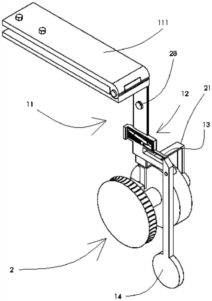
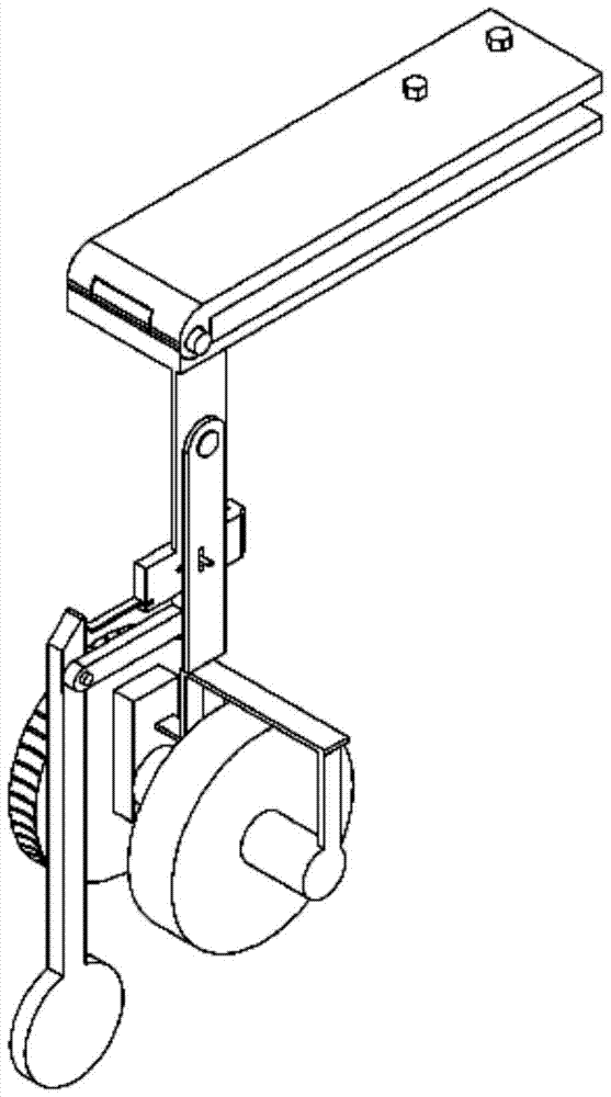
[0034] Gravity clutch device: (see Figure 1 to Figure 6 ) This device is mainly to automatically control whether to supplement energy to the flywheel battery according to the running situation of the bicycle. It includes a mounting frame 11, a clip 111, a self-locking mechanism 12, a push rod 13 and a weight rod 14; the mounting frame 11 is fixedly connected with the rear frame 71 of the bicycle through the clip 111.

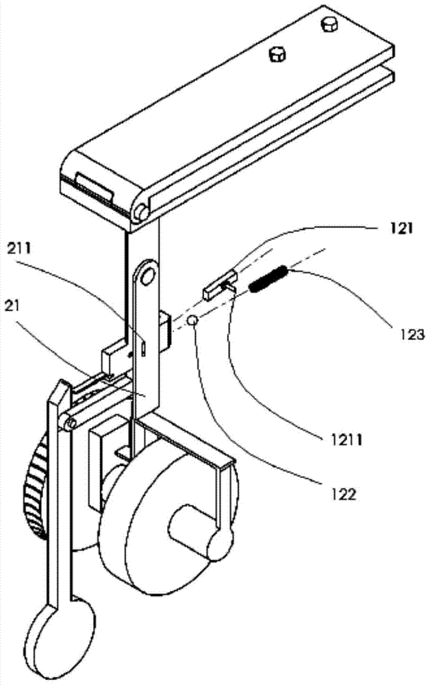
[0035] The self-locking mechanism 12 is fixed on the mounting frame 11 (see Image 6 and Figure 7 ); The self-locking mechanism includes a slider 121, a steel ball 122 and a spring 123. In the illustrated state, the slider 121 can only move to the left. This is because the steel ball 122 presses the slide block 121 against the wedge seam 129, so the slide block 121 cannot move to the right, thereby forming a self-locking state. ...


PUM


Abstract

Disclosed are an apparatus for generating electrical power by a bicycle under gravity control and replenishing energy in a flywheel battery. The bicycle is provided with a gravitational engaging and disengaging device and a motive power assembly (2), wherein the gravitational engaging and disengaging device automatically controls whether to replenish energy in a flywheel battery (3) according to the state of travel of the bicycle. The motive power assembly uses the motive power of a bicycle rear wheel (72) to generate electrical power, and the generated electrical power drives a flywheel (31) of the flywheel battery to store energy. The benefit is that in the case of no power source, the bicycle can be used to replenish kinetic energy in the flywheel battery. Gravity and a self-locking mechanism (12) are used to automatically control the energy replenished in the flywheel battery so as to lighten the manpower load. That is, when the bicycle is going downhill, the apparatus automatically couples with the bicycle to provide kinetic energy to the flywheel; and when the bicycle is going uphill or travelling along a flat, the apparatus automatically separates from the bicycle to lighten the manpower load.

Description

technical field [0001] The invention relates to the field of flywheel batteries (or called flywheel energy storage devices), in particular to a device for supplementing energy with flywheel batteries. Background technique [0002] Among many energy storage devices, flywheel batteries break through the limitations of chemical batteries and use physical methods to store energy. When the flywheel rotates at a certain angular velocity, it has a certain kinetic energy, and the flywheel battery converts the kinetic energy into electrical energy. Compared with chemical batteries, flywheel batteries are expected to become the most promising energy storage batteries due to their outstanding advantages such as high efficiency, short charging time, relatively small size, clean and pollution-free. [0003] The working principle of the flywheel battery: There is a motor (electric / generator integrated machine) in the flywheel battery. When charging, the motor operates in the form of a mo...

Claims


Application Information

Patent Timeline
Patent Type & Authority Patents(China)
IPC IPC(8): B62M6/40
CPCB60L50/20B60L50/30B60L2200/12B62J6/08Y02T10/70
Inventor 柳超
Owner 嘉善联睿电子科技有限公司
Learn More