
An automatic dispensing method and device applicable to various products

An automatic dispensing and dispensing technology, applied in the field of automation, can solve problems such as inability to dispensing different workpieces, long preparation time, etc., to achieve the effects of saving resource consumption, improving production efficiency, and reducing manpower load

Active Publication Date: 2020-09-01
珠海诚锋电子科技有限公司
View PDF5 Cites 0 Cited by
  • Summary
  • Abstract
  • Description
  • Claims
  • Application Information

AI Technical Summary

Problems solved by technology

[0003] In order to overcome the problems that the existing dispensing method requires long preparation time and cannot dispens glue for different workpieces in the same batch, the embodiment of the present invention provides an automatic dispensing method suitable for various products, including:

Method used


Image

  • An automatic dispensing method and device applicable to various products

Examples


no. 1 example

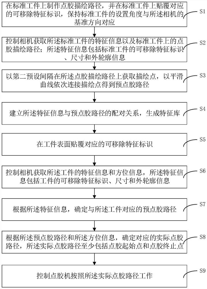
[0057] Please refer to figure 1 As shown, the embodiment of the present invention provides an automatic dispensing method applicable to various products, including:

[0058] S1, making a dispensing drawing path on the standard workpiece, and pasting the corresponding removable feature mark on the standard workpiece, keeping the setting angle of the standard workpiece corresponding to the reference direction of the camera;

[0059] The standard workpiece is used to provide a pre-dispensing path for subsequent workpieces with the same feature information. The dispensing drawing path can be a stroke path or a path formed by punching. In this embodiment, the camera is a line array camera. The removable feature mark is a digital mark or a graphic mark, and the outer edge of the identifiable feature mark can use eye-catching colors, laser stripes, and mirror materials so that the camera can quickly capture the location. When graphic identification is adopted, the graphics in differen...

no. 2 example

[0116] The embodiment of the present invention provides an automatic dispensing device suitable for various products, including:

[0117] The acquisition module is connected with the first determination module, and is used to control the camera to acquire the feature information and orientation information of the workpiece, the feature information includes the removable feature identification, size and outer contour information of the workpiece; the removable feature The logo is pasted on the surface of the workpiece;

[0118] The first determination module is connected with the second determination module, and is used to determine the pre-dispensing path corresponding to the workpiece according to the feature information;

[0119] The second determining module is connected with the control module, and is used to determine the corresponding actual dispensing path according to the pre-dispensing path and the orientation information, and the actual dispensing path includes at le...


PUM


Abstract

The invention discloses an automatic glue-dispensing method suitable for various products. The automatic glue-dispensing method comprises the following steps: attaching a removable feature identifiercorresponding to a workpiece to the surface of the workpiece; controlling a camera to obtain the feature information and orientation information of the workpiece, wherein the feature information includes the information about the removable feature identifier, dimensions and outer contour of the workpiece; according to the feature information, determining a glue pre-dispensing path corresponding tothe workpiece; according to the glue pre-dispensing path and the orientation information, determining a corresponding actual glue-dispensing path, which at least includes a glue-dispensing start point and a glue-dispensing end point; and controlling a glue-dispensing device to work according to the actual glue-dispensing path. The glue-dispensing device uses the automatic glue-dispensing method.The automatic glue-dispensing method and device save manpower, improve the glue-dispensing efficiency, and can perform glue dispensing on various workpieces of different shapes in real time.

Description

technical field [0001] The invention relates to the field of automation, in particular to an automatic dispensing method and device applicable to various products. Background technique [0002] The existing dispensing equipment usually adopts a fixed angle to place the workpiece to be dispensed, and then controls the dispensing machine to dispensing through the pre-programmed dispensing path. Although this method liberates manpower to a certain extent, it needs to be used for various The dispensing path is manually programmed for the workpiece. The preparation in the early stage is labor-intensive and time-consuming, and usually only one kind of workpiece can be targeted in a batch of processing tasks. When the workpiece needs to be replaced, it is also necessary to switch to different programming to change the corresponding point. Glue path, complicated operation and low efficiency. Contents of the invention [0003] In order to overcome the problems that the existing di...

Claims


Application Information

Patent Timeline
Patent Type & Authority Patents(China)
IPC IPC(8): B05C5/02B05C11/10
CPCB05C5/02B05C11/1015
Inventor 郑明国
Owner 珠海诚锋电子科技有限公司
Learn More