Sight line detection device

A line-of-sight detection and component technology, which is applied in the field of line-of-sight detection devices, can solve problems such as difficulty in covering cameras and light sources, low cover strength, and difficulties, and achieve a good appearance effect

Inactive Publication Date: 2016-03-02
ALPS ALPINE CO LTD
View PDF8 Cites 3 Cited by
  • Summary
  • Abstract
  • Description
  • Claims
  • Application Information

AI Technical Summary

Problems solved by technology

When covering the front of the camera and the light source that are placed close to each other with the same cover, there is a problem that the light emitted from the light source propagates inside the cover, and part of the light is emitted from the cover and is easily detected by the came

Method used


Image

  • Sight line detection device
  • Sight line detection device
  • Sight line detection device

Examples


Embodiment Construction

[0060] (Structure of line-of-sight detection device)

[0061] Such as Figure 7 As shown in the block diagram of , the line-of-sight detection device 1 according to the embodiment of the present invention is composed of a pair of illumination imaging units 10 and 20 and a calculation control unit CC.

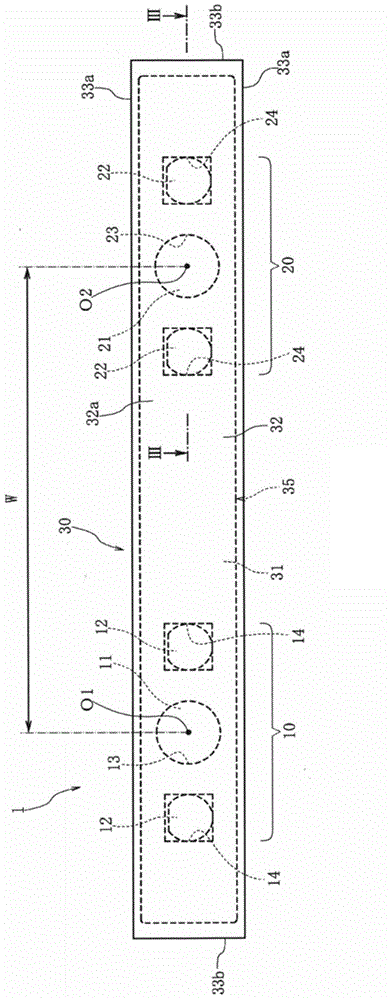
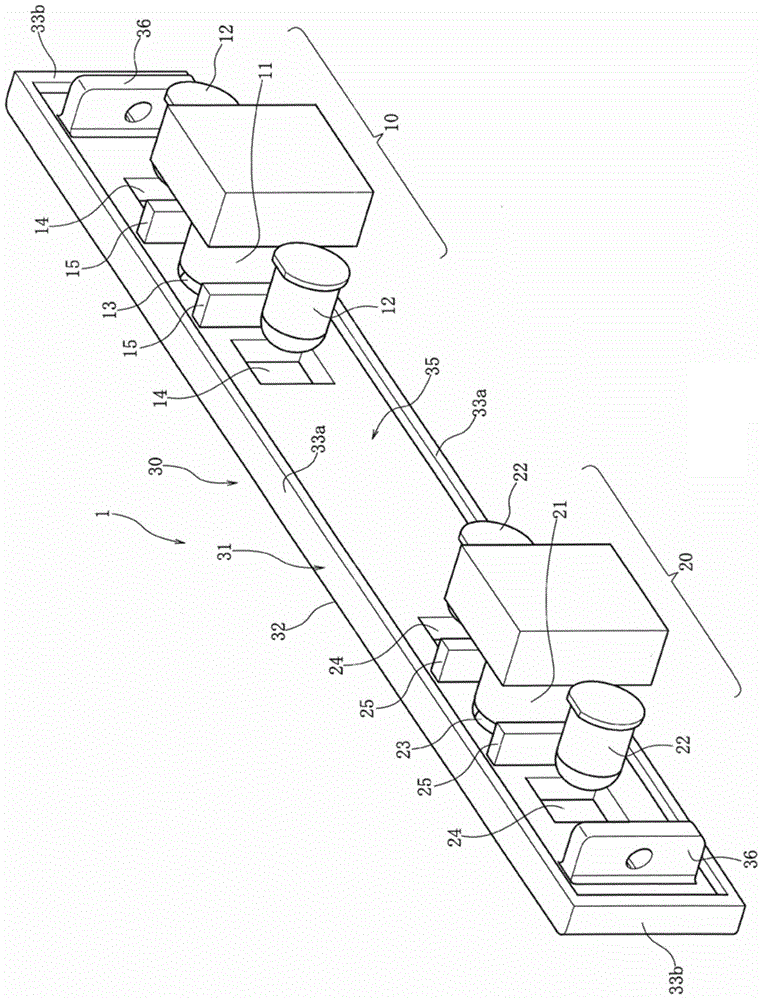
[0062] Such as figure 1 and figure 2 As shown, the common front part 30 is arranged opposite the lighting camera 10 and the lighting camera 20 . The illumination imaging unit 10 is arranged at a distance W from the center of the illumination imaging unit 20 , but the distance W is set to match the distance between human eyes, for example.

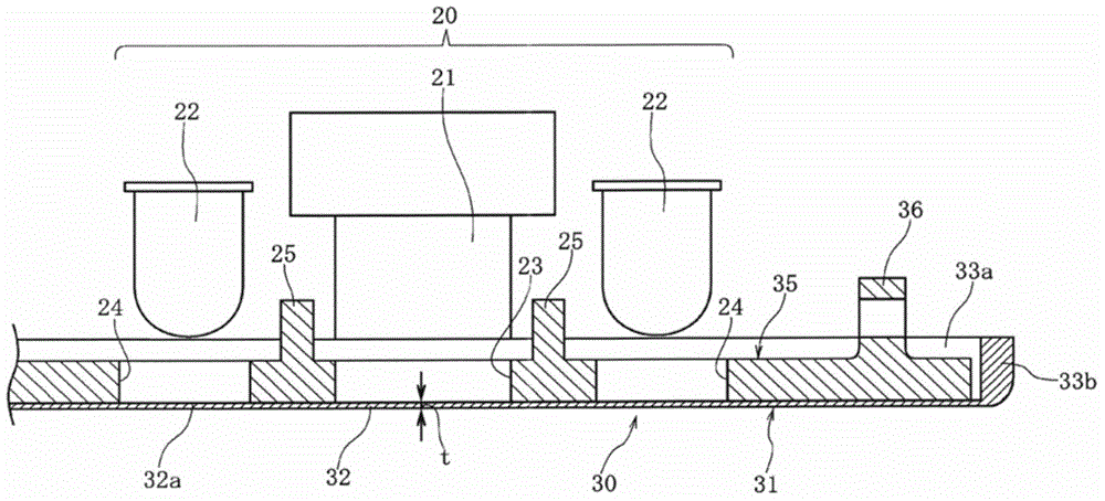
[0063]The illumination imaging unit 10 has a camera 11 and a pair of light sources 12 and 12 disposed close to both sides of the camera 11 , and the illumination imaging unit 20 has a camera 21 and a pair of light sources 22 and 22 disposed close to both sides of the camera 21 . The optical axis of the illumination imaging unit 10 (optic...


PUM

PropertyMeasurementUnit
Thicknessaaaaaaaaaa

Abstract

The invention provides a sight line detection device. A light transmitting part before a light source and a camera is thin, and the strength can be guaranteed. An illuminating camera part (20) comprises a camera (21) and a light source (22). A front part (30), which is covered on the illuminating camera part (20), is formed by tightly connected a light transmitting part (31) and a light shielding part (35) through a bicolor moulding technology. So the strength can be guaranteed, even the thickness (t) of the covered part (32) in the front of light transmitting part (31) is less than 2 mm in front of the camera hole (23). By configuring a thin front covered part (32), the light emitted by the light source (22) will only propagate in the front covered part (32), and will not be emitted to the camera (21); and thus the phenomenon that the light is directly provided to the camera (21) is prevented.

Description

technical field [0001] The present invention relates to a line-of-sight detection device capable of detecting the line-of-sight direction of a target person other than a driver of a vehicle. Background technique [0002] In the gaze point detection method described in Patent Document 1, two cameras are directed toward the eyes of the subject. Two types of light sources are arranged concentrically around each camera. A light source emitting light with a center wavelength of 850 nm is arranged along the inner circle near the camera, and a light source emitting light with a center wavelength of 950 nm is arranged along the outer circle. light source. By irradiating light of 850 nm, images of bright pupils can be acquired by the camera, and images of dark pupils can be acquired by irradiating light of 950 nm. [0003] In this fixation point detection method, a pupil image is obtained based on a difference image between a bright pupil image and a dark pupil image, and a corneal...

Claims


Application Information

Patent Timeline
IPC IPC(8): A61B3/113G06K9/00
Inventor 安田勇一河内隆宏
Owner ALPS ALPINE CO LTD
Why Eureka
Try Eureka