Supercharge Your Innovation With Domain-Expert AI Agents!

Work method of wedge type punching device

The technology of a punching device and working method, which is applied in the field of oblique wedge punching devices, can solve the problems of side wall damage, high cost, and complex punching machine structure, and achieve the effect of avoiding excessive punching force and simple structure

Inactive Publication Date: 2016-03-02
CHONGQING XIN CHUAN TA IND
View PDF0 Cites 4 Cited by
  • Summary
  • Abstract
  • Description
  • Claims
  • Application Information

AI Technical Summary

Problems solved by technology

In order to realize the connection between pipes or the communication between pipes, it is often necessary to punch holes on the side of the pipes. The equipment used includes punching machines. The problems of existing punching machines are: 1. Using independently arranged clamps The clamping mechanism and the stamping mechanism, and a separate power source is required to provide power for the clamping mechanism, resulting in a complex structure and high cost of the punching machine
2. The punching head is basically set vertically, and the punching is directly driven by the power machine. There is often a problem that the punching force is too large. When only punching one side of the hole, it often causes damage to the side wall on the other side.

Method used


Image

  • Work method of wedge type punching device

Examples


Embodiment Construction

[0017] The present invention is described in further detail below by specific embodiments:

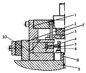
[0018] The reference signs in the accompanying drawings include: wedge 1, seat plate 2, pressure plate 3, slider 4, stamping head 5, guide plate 6, rubber pad 7, positioning plate 8, mounting seat 9, guide block 10.

[0019] The embodiment of oblique wedge type punching device is basically as attached figure 1 Shown: In the wedge-type punching device of this embodiment, the mounting seat is located at the bottom, and the seat plate, guide block and positioning plate are fixed on the mounting seat in sequence from left to right, and a rubber pad is provided on the left side of the seat plate . There is a horizontal through groove on the guide block, the slider is located in the through groove, the slider is matched with the sliding sleeve of the through groove, and a tension spring is connected between the side of the slider and the seat plate, and the pull ring has the function of res...


PUM


Abstract

The invention discloses a work method of a wedge type punching device for pipe fitting punching. The device is simple in structure, provides clamping force through a punching plate and can not exert large punching force on pipe fittings. The work method of the wedge type punching device for pipe fitting punching includes the following steps that firstly, the pipe fittings are placed on an arc-shaped face on the upper portion of a positioning plate to be positioned; secondly, under drive of a power machine, the punching plate moves downwards and drives an elastic element and a wedge to vertically move downwards; thirdly, the elastic element makes contact with and abuts against a pressing plate, and the pressing plate presses the pipe fittings on the positioning plate; fourthly, the first inclined face of the wedge abuts against the second inclined face of a sliding block, so that the sliding block is forced to drive a punch to move to the pipe fittings in the horizontal direction and punch the pipe fittings; fifthly, after a stroke is in place, the punching plate moves upwards and drives the elastic element and the wedge to vertically move upwards; sixthly, the sliding block automatically returns to the original position, the elastic element loosens the pressing plate, the pressing plate loosens the pipe fittings, the pipe fittings are taken down from the positioning plate, and one time of punching is completed; and seventhly, punching of the pipe fittings is completed by repeating the preceding six steps.

Description

technical field [0001] The invention relates to the punching technology of pipe materials, in particular to a working method of a wedge type punching device. Background technique [0002] Pipe is a commonly used mechanical component. It is widely used in construction engineering. Commonly used are water supply pipes, drainage pipes, gas pipes, heating pipes and rainwater pipes. In order to realize the connection between pipes or the communication between pipes, it is often necessary to punch holes on the side of the pipes. The equipment used includes punching machines. The problems of existing punching machines are: 1. Using independently arranged clamps The clamping mechanism and the stamping mechanism need to be separately provided with a power source to provide power for the clamping mechanism, resulting in a complex structure and high cost of the punching machine. 2. The stamping head is basically vertically set, and the punching is directly driven by the power machine,...

Claims


Application Information

Patent Timeline
IPC IPC(8): B21D28/28B21D28/34
Inventor 徐科
Owner CHONGQING XIN CHUAN TA IND
Features
  • R&D
  • Intellectual Property
  • Life Sciences
  • Materials
  • Tech Scout
  • Unparalleled Data Quality
  • Higher Quality Content
  • 60% Fewer Hallucinations
Learn More