Angle-adjustable valve positioning mechanism

A valve positioning and angle technology, which is applied in the field of tooling and fixtures, can solve the problems of increasing cost, unable to clamp and position, and unable to adapt to the valve body, etc., to achieve the effect of convenient clamping and positioning and ensuring processing.

Inactive Publication Date: 2016-03-02
CHONGQINGZHICHENG MACHINERY CO LTD
View PDF8 Cites 7 Cited by
  • Summary
  • Abstract
  • Description
  • Claims
  • Application Information

AI Technical Summary

Problems solved by technology

[0003] At present, most valves have horizontal flange surfaces at both ends, which are convenient for processing and positioning; with the demand of the market, there have been valve bodies with one end flange as a horizontal surface and the other end flange as an inclined surface, which cannot be achieved by using conventional tooling. Clamping and positioning, it is not convenient to process the horizontal flange surface, and the traditional tooling cannot adapt to the valve body with different inclination angles, each type of valve body must make a separate tooling, which increases the cost

Method used


Image

  • Angle-adjustable valve positioning mechanism
  • Angle-adjustable valve positioning mechanism

Examples


Embodiment Construction

[0037] The implementation of the present invention will be illustrated by specific specific examples below, and those skilled in the art can easily understand other advantages and effects of the present invention from the contents disclosed in this specification.

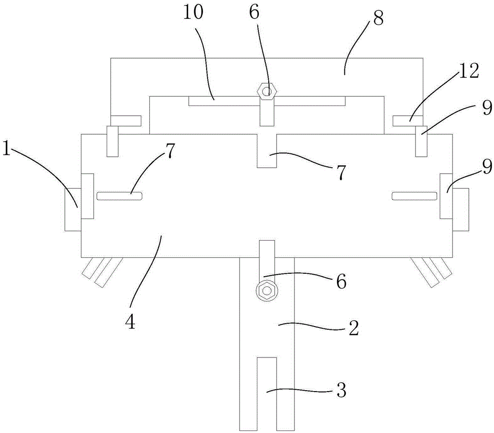
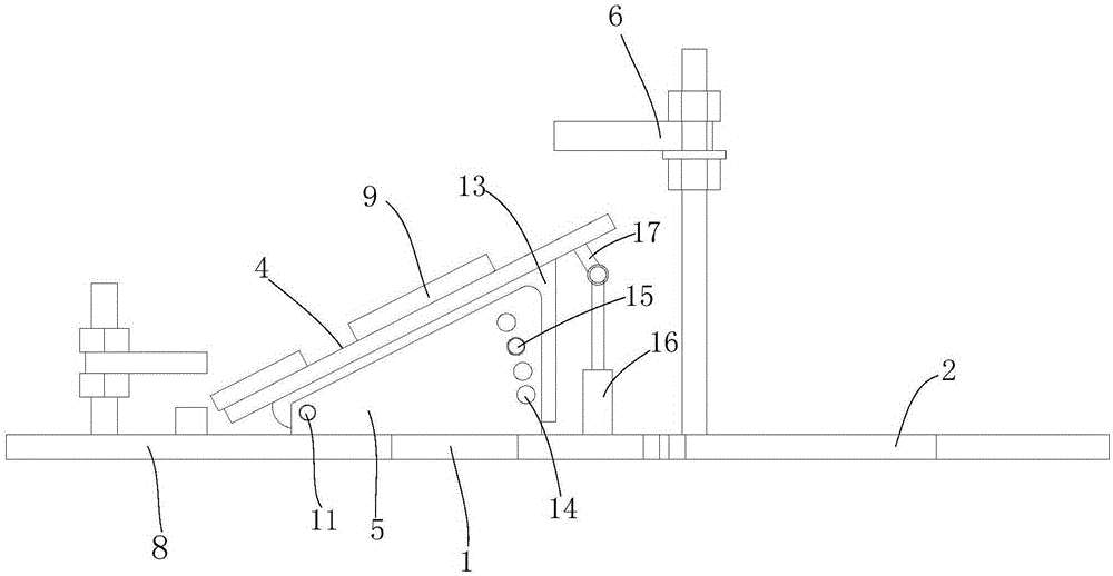
[0038] like Figure 1 to Figure 2 As shown, an angle-adjustable valve positioning mechanism includes a base 1, a support plate 4 and a pressing mechanism 6. The base is provided with two inclined support blocks 5, and the support plate is installed on the support block with a low front and a high rear. 5, the bottom of the support plate is provided with two adjustment plates 13 corresponding to the support block 5, the front portion of the adjustment plate 13 is rotationally connected with the front portion of the support block 5 through the rotating shaft 11, and the rear portion of the adjustment plate 13 is provided with a locking hole. A plurality of height adjustment holes 14 are opened at the rear of the suppo...


PUM


Abstract

The invention provides an angle-adjustable valve positioning mechanism. The angle-adjustable valve positioning mechanism comprises a base, a supporting plate and a pressing mechanism, wherein the base is provided with two oblique supporting blocks; the supporting plate is obliquely mounted on the supporting blocks in a manner that the front part is lower than the back part; regulating plates corresponding to the supporting blocks are arranged at the bottom of the supporting plate; the front part of each regulating plate is rotationally connected with the front part of each supporting block by a rotating shaft; the rear part of each regulating plate is provided with a locking hole; the rear part of each supporting block is provided with a plurality of height regulating holes; the regulating plates and the supporting blocks are fixed by positioning pin shafts which penetrate into the height regulating holes and the locking holes. During use of the angle-adjustable valve positioning mechanism disclosed by the invention, an oblique flange surface of an oblique valve body is supported on the supporting plate and is primarily positioned by a bolt and a positioning hole; the side surface of the valve body is shielded by a positioning block, and then the valve body is pressed by a pressing mechanism; the supporting plate can rotate about the rotating shaft by virtue of the regulating plates to regulate the angle so as to adapt to clamping of valve bodies at different inclination angles.

Description

technical field [0001] The invention belongs to the technical field of fixtures, in particular to an angle-adjustable valve positioning mechanism. Background technique [0002] A valve is a device used to control the direction, pressure, and flow of a fluid in a fluid system. It is a device that allows the medium (liquid, gas, powder) in the piping and equipment to flow or stop and can control its flow. The processing accuracy of the valve directly affects the sealing performance of the entire pipeline. [0003] At present, most valves have horizontal flange surfaces at both ends, which are convenient for processing and positioning; with the demand of the market, there have been valve bodies with one end flange as a horizontal surface and the other end flange as an inclined surface, which cannot be achieved by using conventional tooling. Clamping and positioning are not convenient for processing horizontal flange surfaces, and traditional tooling cannot adapt to valve bodie...

Claims


Application Information

Patent Timeline
Patent Type & Authority Applications(China)
IPC IPC(8): B23Q3/04
CPCB23Q3/04
Inventor 孙仁坤
Owner CHONGQINGZHICHENG MACHINERY CO LTD
Why Eureka
Try Eureka