Product positioning and clamping mechanism

A positioning clamping and product technology, applied in the direction of workpiece clamping devices, manufacturing tools, etc., can solve the problems of uncoordinated movements of multiple power sources, inaccurate positioning, complex structures, etc., and achieve coordinated and synchronized actions, improved efficiency, Simple operation effect

Active Publication Date: 2016-03-02
BOZHON PRECISION IND TECH CO LTD
View PDF6 Cites 8 Cited by
  • Summary
  • Abstract
  • Description
  • Claims
  • Application Information

AI Technical Summary

Problems solved by technology

[0002] The existing product positioning and clamping mechanisms generally use a power source to drive the clamping block to clamp the side of the product. Multiple power sources are required for different sides of the product, and its structure is relatively complicated. It is impossible to realize the clamping of two workstations through one power source. At the same time, the actions of multiple power sources are not coordinated or synchronized, and it is impossible to accurately locate the product in the process of positioning

Method used


Image

  • Product positioning and clamping mechanism
  • Product positioning and clamping mechanism
  • Product positioning and clamping mechanism

Examples


Embodiment Construction

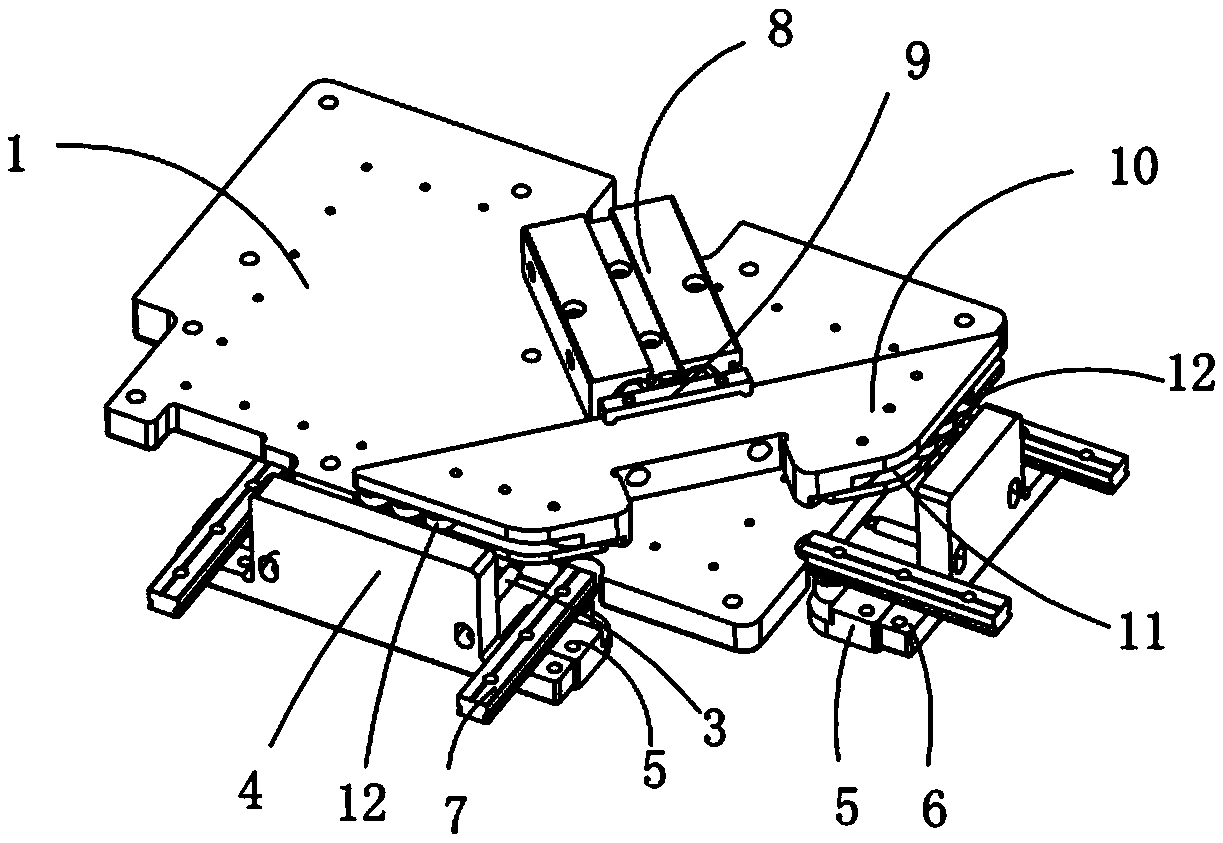
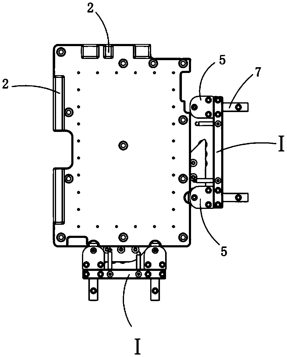
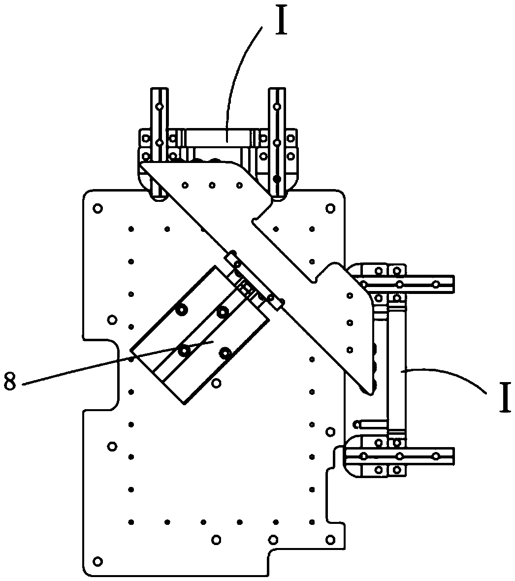
[0018] Examples, see attached Figure 1~3 , a product positioning clamping mechanism, including a bearing plate 1, the upper part of the bearing plate is provided with a rib 2, and the rib is located at the upper left side or the upper rear side of the bearing plate.

[0019] The front part and the right part of the bearing plate are respectively provided with an elastic mechanism I, and the elastic mechanism includes a spring 3, a sliding block 4 and a collet 5, and the sliding block is installed on the front side or the right side of the bearing plate through a spring; The sliding block is a convex structure, and chucks are respectively installed at the positions of flanges 6 on both sides of the convex structure, and the lower bottom surface of the chuck is higher than the upper surface of the loading plate, and the product is placed on the loading plate, and the chuck can Product clamping;

[0020] The bottom of the sliding block is mounted on the guiding mechanism; the g...


PUM


Abstract

The invention relates to a product positioning and clamping mechanism. The front portion and the right portion of a bearing plate are each provided with an elastic mechanism. Each elastic mechanism comprises springs, a sliding block and clamping heads, wherein the sliding block is installed on the front side or the right side of the bearing plate through the springs; the sliding block is in an inverted-T shape; the clamping heads are installed in the positions of flanges on the two sides of the inverted-T-shaped structure respectively; the lower bottom face of each clamping head is higher than the upper surface of the bearing plate. A product is placed on the bearing plate. The clamping heads can clamp the product. The bottom of each sliding block is installed on a guiding mechanism in a matched mode. A power source is installed at the bottom of the bearing plate. The front end of a piston rod of the power source is connected with a push block. The push block is of an isosceles trapezoid structure, and the two oblique side faces of the isosceles trapezoid structure are perpendicular. Grooves are formed in the oblique side faces of the isosceles trapezoid structure respectively. A plurality of sets of idler wheels are installed in each groove. The power source drives the push block to move so that the idler wheels can make contact with the sliding blocks and push the sliding blocks to move along the guiding mechanisms, and the product is clamped or loosened under the action of the springs.

Description

Technical field: [0001] The present invention relates to the field of positioning and clamping equipment, and more specifically relates to a positioning and clamping mechanism that simultaneously realizes the actions of two workstations through a process of mutual switching between a power source and an elastic mechanism. Background technique: [0002] The existing product positioning and clamping mechanisms generally use a power source to drive the clamping block to clamp the side of the product. Multiple power sources are required for different sides of the product, and its structure is relatively complicated. It is impossible to realize the clamping of two stations through one power source. At the same time, the actions of multiple power sources are not coordinated or synchronized, and the positioning of the product cannot be accurately positioned. Invention content: [0003] The purpose of the present invention is to provide a product positioning and clamping mechanism...

Claims


Application Information

Patent Timeline
Patent Type & Authority Applications(China)
IPC IPC(8): B25B11/00
CPCB25B11/00
Inventor 吕绍林杨愉强王建福刘建军
Owner BOZHON PRECISION IND TECH CO LTD
Why Eureka
Try Eureka