Full-automatic die cutting machine

A die-cutting machine, fully automatic technology, applied in the direction of metal processing, etc., can solve the problems of long adjustment time, incomplete cutting of the label layer, and bottom layer breakage, etc., to achieve short adjustment time, accurate adjustment of the relative position of the cutter, and convenient adjustment time Effect

Active Publication Date: 2016-03-02
SUZHOU INDAL PARK TEAMS TECH
View PDF5 Cites 8 Cited by
  • Summary
  • Abstract
  • Description
  • Claims
  • Application Information

AI Technical Summary

Problems solved by technology

State-of-the-art die-cutting machines such as figure 1 As shown, it mainly includes a frame 1, a feeding device 2, a die-cutting device 3, a receiving table 4, a waste reel 5 and a reel 6, the feeding device is arranged on the rear side of the frame, and the die-cutting device is set On the top side of the middle of the frame, the receiving table is set on the front side of the frame. The material usually includes the bottom layer and the label layer attached to the bottom layer. The upper relative position is adjustable and the cutter rotates relatively. The feeding device transports the strip material to the roller of the die-cutting device and the cutter for die-cutting. Accordi

Method used


Image

  • Full-automatic die cutting machine
  • Full-automatic die cutting machine
  • Full-automatic die cutting machine

Examples


Embodiment Construction

[0022] The specific implementation manners of the present invention will be further described in detail below in conjunction with the accompanying drawings and embodiments. The following examples are used to illustrate the present invention, but are not intended to limit the scope of the present invention.

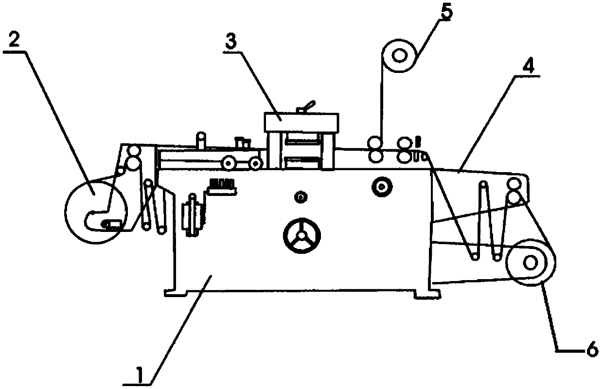
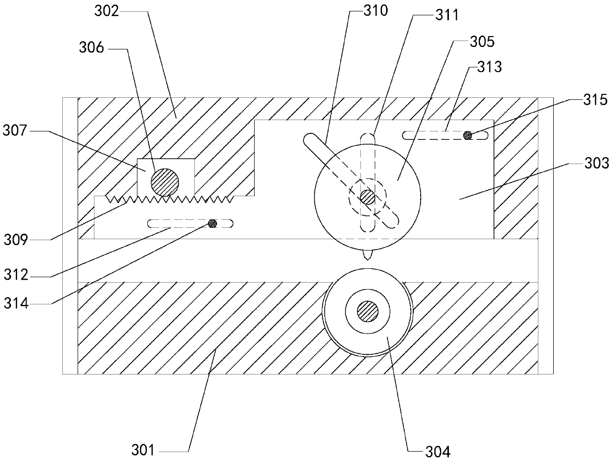
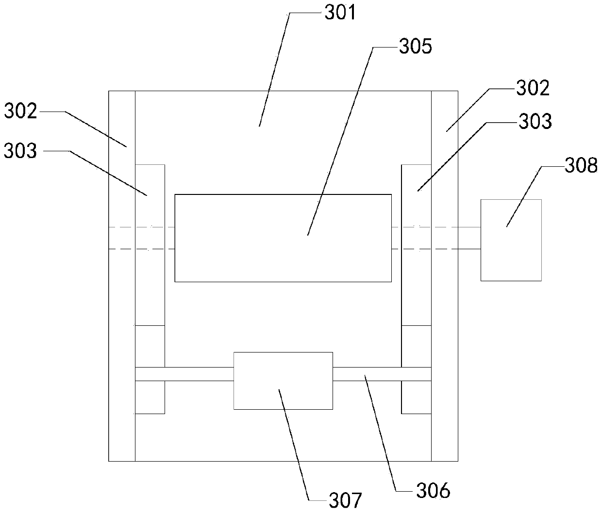
[0023] see Figure 1 to Figure 4 , a kind of fully automatic die-cutting machine of a preferred embodiment of the present invention, comprises the frame 1 identical with the prior art, feeding device 2, receiving table 4, waste reel 5 and rewinding reel 6, additionally to The die-cutting device 3 is further improved, wherein the die-cutting device 3 includes a base 301, a pair of side plates 302 oppositely arranged on both sides of the base, a pair of sliding plates 303 located on the inside of the side plates 302 and relatively sliding, arranged on the base 301 The inner relatively rotating roller 304, the cutter 305 above the roller 304, the transmission shaft 306, the ...


PUM


Abstract

The invention relates to a die cutting machine, in particular to a full-automatic die cutting machine. The full-automatic die cutting machine comprises a machine frame, a feeding device, a die cutting device, a material receiving platform, a waste material winding barrel and a material receiving roll. The die cutting device comprises a base, side plates, sliding plates, a roller, a cutter, a transmission shaft, a first power unit and a second power unit; the sliding plates are provided with racks, teeth engaged with the racks are arranged on the two sides of the transmission shaft, and the first power unit is in transmission connection with the transmission shaft; sliding limiting devices are arranged between the side plates and the sliding plates and used for limiting the relative motion of the sliding plates on the side plates in the horizontal direction, the sliding plates are aslant provided with strip-shaped limiting holes, and the side plates are provided with strip-shaped sliding holes in the vertical direction; the two ends of the cutter penetrate through the limiting holes and the sliding holes in sequence, and the second power unit is in transmission connection with the cutter. According to the full-automatic die cutting machine, the relative position of the cutter can be adjusted precisely, the adjustment time is short, the time is convenient to adjust, and the number of produced waste materials is small.

Description

technical field [0001] The invention relates to a die-cutting machine, in particular to an automatic die-cutting machine. Background technique [0002] The die-cutting machine is mainly used for die-cutting (full-cut, half-cut), indentation and bronzing of some non-metallic materials, self-adhesive, double-sided tape, electronic or mobile phone rubber pads, trademark labels, etc. Important equipment for packaging processing and molding. State-of-the-art die-cutting machines such as figure 1 As shown, it mainly includes a frame 1, a feeding device 2, a die-cutting device 3, a receiving table 4, a waste reel 5 and a reel 6, the feeding device is arranged on the rear side of the frame, and the die-cutting device is set On the top side of the middle of the frame, the receiving table is set on the front side of the frame. The material usually includes the bottom layer and the label layer attached to the bottom layer. The upper relative position is adjustable and the cutter rot...

Claims


Application Information

Patent Timeline
IPC IPC(8): B26F1/38B26D7/26B26D5/08
Inventor 钱洪海
Owner SUZHOU INDAL PARK TEAMS TECH
Why Eureka
Try Eureka