An installation structure of an adjustable sealing strip and a leakage gate

A technology for installing structures and sealing strips, used in sealing devices, windows/doors, building components, etc., can solve problems such as high cost, poor wall flatness, and difficulty, and achieve precise and convenient micro-adjustment operations. Gap error, the effect of increasing the amount of deformation

Active Publication Date: 2022-07-05
SCIMEE TECH & SCI CO LTD
View PDF15 Cites 0 Cited by
  • Summary
  • Abstract
  • Description
  • Claims
  • Application Information

AI Technical Summary

Problems solved by technology

The traditional discharge gate uses a rubber strip to fit the edge of the gate to achieve sealing. The structure of the rubber strip is relatively simple, and the position is fixed after installation, so adaptive fine-tuning cannot be performed.
During the rotation of the gate, the rubber strip rubs against the wall surface, which will cause certain wear and tear; and the wall of the weir where the discharge gate is installed is affected by factors such as water soaking and impact, and the flatness of the wall surface is poor, which makes the traditional discharge gate After using for a certain period of time, there will be problems such as poor sealing and water leakage.
At this time, usually only the way of replacing the rubber strip can be used for maintenance, which is more difficult and costly

Method used


Image

  • An installation structure of an adjustable sealing strip and a leakage gate
  • An installation structure of an adjustable sealing strip and a leakage gate
  • An installation structure of an adjustable sealing strip and a leakage gate

Examples


Embodiment 1

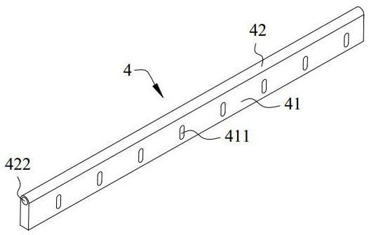
[0050] see figure 1 , the embodiment of the present invention provides an adjustable sealing strip, the sealing strip 4 includes a body extending along the length direction of the sealing strip, and the body includes a mounting part 41 and a sealing part 42 .

[0051] The mounting portion 41 extends along the length direction of the weather strip, and is provided with a plurality of waist holes 411 at intervals along the length direction of the weather strip. The length direction of the waist holes 411 is perpendicular to the length direction of the weather strip, several waist holes 411 are parallel to each other, and all the waist holes 411 pass through the mounting portion 41 of the weather strip 4 .

[0052] A real-time method is that a plurality of waist holes 411 are equally spaced and evenly distributed on the mounting portion 41 of the sealing strip 4 , which can better adjust the installation position of each part of the sealing strip 4 .

[0053] The sealing portion 4...

Embodiment 2

[0056] see figure 2 , Figure 7 to Figure 10 , the embodiment of the present invention provides an adjustable sealing strip installation structure, the installation structure includes a sealing strip 4, a mounting plate 5, a pressing plate 6 and a clamping assembly 7 and the like.

[0057] The sealing strip 4 is the sealing strip described in the first embodiment above.

[0058] The mounting plate 5 is in the shape of a long strip, which is matched with one side of the mounting portion 41 of the sealing strip 4. When the sealing strip 4 is assembled on the mounting plate 5, its sealing portion 42 extends to the outside of the mounting plate 5 to achieve deformation sealing Function.

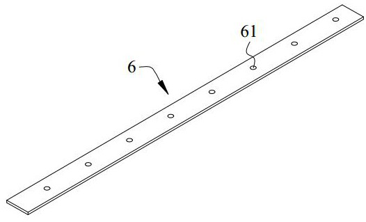
[0059] The pressing strip 6 is in the shape of a long strip, which is matched with the other side of the mounting portion 41 of the sealing strip 4 , and is used for clamping the sealing strip 4 in cooperation with the mounting plate 5 .

[0060] The clamping assembly 7 includes a first screw...

Embodiment 3

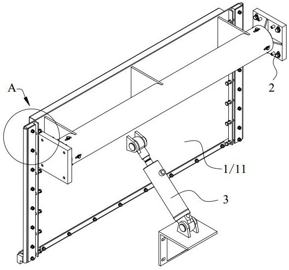
[0068] see Figure 3 to Figure 10 , the embodiment of the present invention provides a leakage gate, which includes a door panel 1 , a support base 2 , a drive assembly 3 and the like.

[0069] The size of the door panel 1 is adapted to the weir mouth for intercepting the water flow. The support base 2 is fixedly installed on the side wall of the weir mouth, and is rotatably connected with the door panel 1 for supporting the door panel 1 . The drive assembly 3 is connected with the door panel 1 and is used to drive the door panel 1 to rotate around the support base 2 to realize the opening or closing of the lower end of the door panel 1 .

[0070] The door panel 1 is provided with a first pressure bearing surface 11 and a second pressure bearing surface 12, and the first pressure bearing surface 11 and the second pressure bearing surface 12 correspond to the upstream and downstream of the water flow at the weir, respectively. The edge of the first pressure-bearing surface 11...


PUM


Abstract

The invention relates to an adjustable sealing strip installation structure and a leakage gate. The sealing strip comprises: an installation part extending along the length direction of the sealing strip and provided with a plurality of waist holes; the sealing part attached to one side of the installation part , whose side surfaces are curved surfaces. The installation structure includes: a sealing strip; an installation plate, which is adapted to one side of the installation part, and the sealing part extends to the outside of the installation plate; a pressure strip, which is adapted to the other side of the installation part; a clamping assembly, including a first screw rod and a first nut The mounting plate and the pressure strip are provided with mounting holes, and the mounting holes correspond to the waist holes one-to-one; The discharge gate includes: a door panel; the door panel is provided with a first pressure-bearing surface and a second pressure-bearing surface, and the edge of the first pressure-bearing surface is provided with the above-mentioned installation structure. The installation structure can fine-tune different parts of the sealing strip, so that the sealing performance of the leakage gate using the sealing strip and its installation structure is improved, maintenance is convenient, and maintenance costs are saved.

Description

technical field [0001] The invention relates to the technical field of water supply and drainage engineering equipment, in particular to an installation structure of an adjustable sealing strip and a discharge gate. Background technique [0002] In municipal drainage projects, in order to achieve source control and interception, waterlogging prevention and control, rainwater utilization and other purposes, interception and storage facilities are usually set up in the drainage system to effectively control rainwater confluence, overflow, pollution and other problems, and ensure the drainage system. It is stable and safe, and at the same time improves the efficiency of sewage treatment and the utilization rate of rainwater. [0003] There are various gates to control the water flow in the regulating reservoirs, interception wells and other facilities of the drainage system. According to the function of the gates, they are divided into flow regulating gates, overflow gates, dis...

Claims


Application Information

Patent Timeline
Patent Type & Authority Patents(China)
IPC IPC(8): E06B7/23E06B7/28E02B5/08
CPCE06B7/23E06B7/28E02B5/08Y02E10/50
Inventor 肖波汤杰佟斯翰易洋王哲晓
Owner SCIMEE TECH & SCI CO LTD
Why Eureka
Try Eureka