

Wearable apparatus
A display device and wearable technology, applied in optical components, instruments, optics, etc., can solve the problems of insufficient light weight and superior wearability, and achieve the effects of suppressing the increase in product weight, suppressing the decrease in characteristics, and suppressing heat generation.
- Summary
- Abstract
- Description
- Claims
- Application Information
AI Technical Summary
Problems solved by technology
Method used
Image

Examples
no. 1 approach
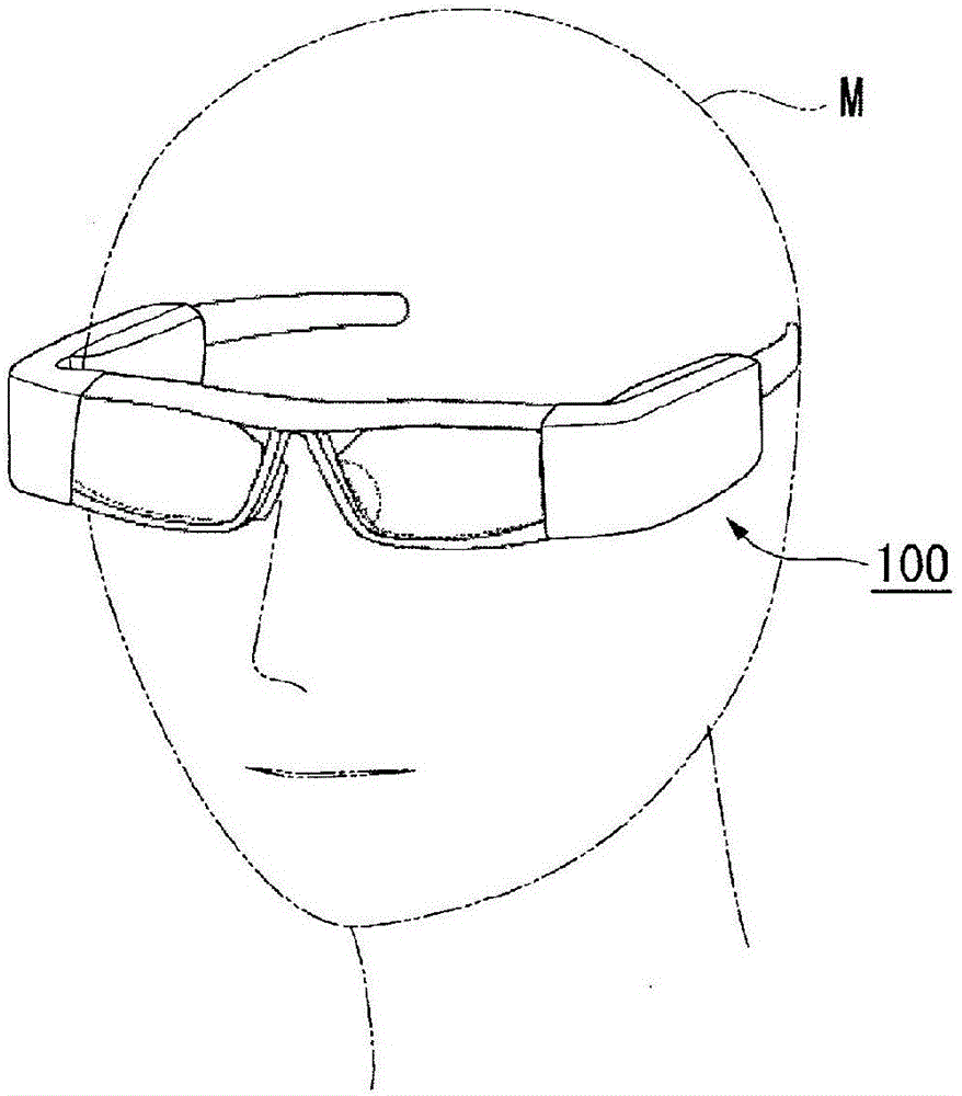
[0043] figure 1 It is a figure showing the usage form of HMD100. Such as figure 1 As shown, the HMD 100 of this embodiment is used by being worn on the head of the observer M. As shown in FIG.
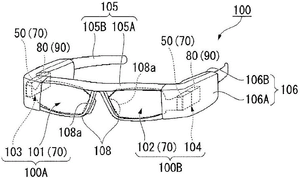
[0044] figure 2 It is a figure which shows the schematic structure of HMD100.
[0045] Such as figure 2 As shown, HMD 100 includes first optical member 101 , second optical member 102 , first image forming unit 103 , second image forming unit 104 , and housing 105 , which cover eyes of an observer in a see-through manner.
[0046] The first optical member 101 and the second optical member 102 are arc-shaped members curved so as to follow the face of the observer, and each include a light guiding and see-through prism portion, and a see-through light-transmitting portion. The first optical member 101 and the second optical member 102 are formed of a resin material having high light transmittance in the visible range, and are molded, for example, by injecting a thermoplastic resin...
no. 2 approach
[0082] Next, another form of the heat dissipation structure of the display panel 80 will be described as a second embodiment. Figure 5 It is a plan view showing the heat dissipation structure of the display panel 80 according to this embodiment. The difference between this embodiment and the first embodiment lies in the object of heat dissipation in the panel frame 90 , and other structures are common. Therefore, in the following description, the description of the same parts as those in the above-mentioned embodiment will be omitted, and the same reference numerals will be attached to the drawings.
[0083] In the present embodiment, the panel frame transmits heat generated in display panel 80 to exterior member 106 constituting a part of housing 105 of HMD 100 , thereby releasing the heat to the outside.
[0084] Specifically, one of the pair of side plate portions 92 of the panel frame 90 is connected to the inner surface of the outer surface side member 106A via the therma...
no. 3 approach
[0092] Next, another form of the heat dissipation structure of the display panel 80 will be described as a third embodiment. The difference between this embodiment and the first embodiment lies in the heat dissipation structure of the display panel 80 , and other structures are common. Therefore, in the following description, the description of the same parts as those in the above-mentioned embodiment will be omitted, and the same reference numerals will be attached to the drawings.
[0093] Figure 6 It is an exploded perspective view showing the heat dissipation structure of the display panel 80 according to this embodiment.
[0094] Such as Figure 6 As shown, in the present embodiment, the projection lens 50 and the panel frame 190 of the HMD 110 of the present embodiment are unitized. Specifically, the projection lens (optical component) 50 is held by a lens barrel (optical component frame) 51 . The lens barrel 51 has a pair of lower protrusions 51a and upper protrusi...
PUM
 Abstract
Description
Claims
Application Information