
A mounting head and a mounting device

A technology for mounting devices and mounting heads, which is applied in the direction of electrical components, electrical components, etc., can solve the problems of increased weight of the mounting head, larger load, and slower moving speed of the mounting head, and achieve the effects of shortening the stroke and improving production efficiency

Active Publication Date: 2018-03-13
JUKI CORP
View PDF15 Cites 3 Cited by
  • Summary
  • Abstract
  • Description
  • Claims
  • Application Information

AI Technical Summary

Problems solved by technology

[0004] However, since the mounting head described in Patent Document 1 is a heavy object, it is necessary to increase the rigidity of each part of the mounting head by disposing a large drive motor on the mounting head in order to move the mounting head up and down.
In addition, as the size and rigidity of the drive motor increase, the weight of the mounting head increases, so the load when moving the mounting head in the X-axis direction and the Y-axis direction increases, and the horizontal movement speed of the mounting head becomes slower.
As described above, the tact time is shortened by shortening the stroke of the suction nozzle, but on the other hand, the tact time is increased corresponding to the decrease in the moving speed of the mounting head in the horizontal direction.

Method used


Image

  • A mounting head and a mounting device
  • A mounting head and a mounting device
  • A mounting head and a mounting device

Examples


Embodiment Construction

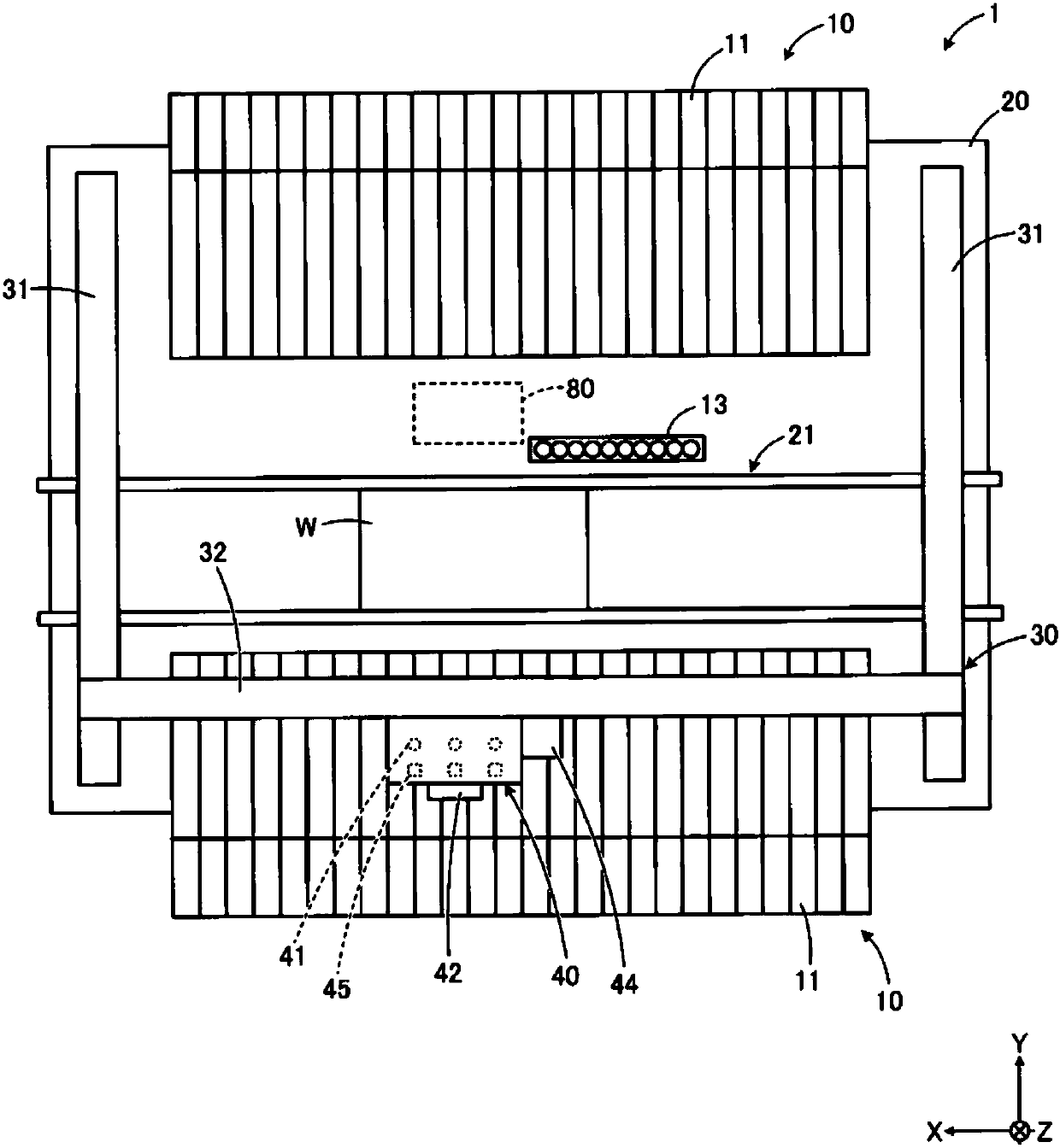
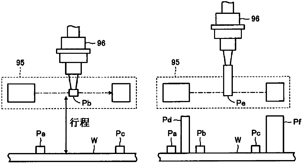
[0057] Next, a mounting device according to a first embodiment will be described with reference to the drawings. figure 1 It is a schematic diagram which shows the whole mounting apparatus of 1st Embodiment. FIG. 2 is an explanatory diagram of a mounting operation of a comparative example. In addition, the attachment device of 1st Embodiment is just an example, and can be changed suitably.

[0058] Such as figure 1 As shown, the mounting apparatus 1 is configured to mount various components supplied from the feeder 10 on predetermined positions on the substrate W via the mounting head 40 . A substrate transport unit 21 for transporting the substrate W along the X-axis direction is arranged substantially at the center of the base 20 of the mounting apparatus 1 . The substrate transfer unit 21 carries in and positions the substrate W before component mounting under the mounting head 40 from one end side in the X-axis direction, and carries out the substrate W after component ...


PUM


Abstract

An increase of the weight of a mounting head is inhibited and a stroke of a suction nozzle is shortened to increase the production efficiency of a substrate. The mounting head (40) for mounting components supplied by a supplier through the suction nozzle to the substrate is provided with a sensor unit (43) recognizing components lifted by the suction nozzle, and a lifting and descending mechanism(70) lifting and descending the sensor unit to allow component recognition height to be variable. The sensor unit is made close to the substrate, thus shortening the stroke of the suction nozzle whenthe suction nozzle allows components lifted to the recognition height of the sensor unit to be lowered to the upper surface of the substrate, shortening production pitch time, and increasing the production efficiency of the substrate.

Description

technical field [0001] The present invention relates to a mounting head and a mounting device for mounting components on a substrate. Background technique [0002] In the mounting head, the component sent out from the feeder is picked up by the suction nozzle, and the suction nozzle is lowered to the mounting position of the substrate to mount the component on the substrate. As this mounting head, the following mounting head is known, that is, by suppressing the height of the mounting head and the upper surface of the substrate as much as possible, thereby reducing the stroke of the suction nozzle and improving the production efficiency of the substrate (for example, refer to Patent Document 1). In the mounting head described in Patent Document 1, the height between the mounting head and the substrate is adjusted according to the height dimension of the component (the type of component), and the stroke of the suction nozzle is shortened, thereby shortening the tact time req...

Claims


Application Information

Patent Timeline
Patent Type & Authority Applications(China)
IPC IPC(8): H05K13/04H05K13/08
CPCH05K13/0413H05K13/08
Inventor 野原伸和松井智仁井桝孝彦安泽昭伸佐藤祐太
Owner JUKI CORP
Learn More