Connector and contact component thereof

A technology of contact parts and contact parts, which is applied in the direction of contact parts, fixed/insulated contact parts, etc., can solve the problems of damaged sealing effect, shortened service life of high-speed four-core differential contact parts, and inability to use glass sealing and sealing structures, etc., to achieve Effect of improving sealing performance

Active Publication Date: 2016-03-02
CHINA AVIATION OPTICAL-ELECTRICAL TECH CO LTD
View PDF8 Cites 12 Cited by
  • Summary
  • Abstract
  • Description
  • Claims
  • Application Information

AI Technical Summary

Problems solved by technology

Due to the limitation of the structural size of each socket-type differential contact in the high-speed four-core differential contact part 15, O-rings cannot be used between the differential contact in the high-speed four-core differential contact part 15 and the front insulator 16 and the rear insulator 17 At the same time, since the fixed sleeve 18 and the differential contact of the high-speed four-core differential contact part 15 are usually made of beryllium copper alloy or tin bronze alloy, which does not match the glass sealing process, there is no way between the differential contact and the fixed sleeve 18. Seal structure with glass seal
The sealing method of the high-speed four-core differential contact part 15 in the prior art is: after the front end of the wire is inserted and crimped on the tail of the differential contact, silicone rubber is potted from the rear end of the fixed sleeve 18 to allow the silicone rubber to solidify. The final insulating colloid realizes the positioning of the sealing box between the differential contacts and between the differential contacts and the fixed sleeve 18, but there are two problems in thi

Method used


Image

  • Connector and contact component thereof
  • Connector and contact component thereof
  • Connector and contact component thereof

Examples


Embodiment Construction

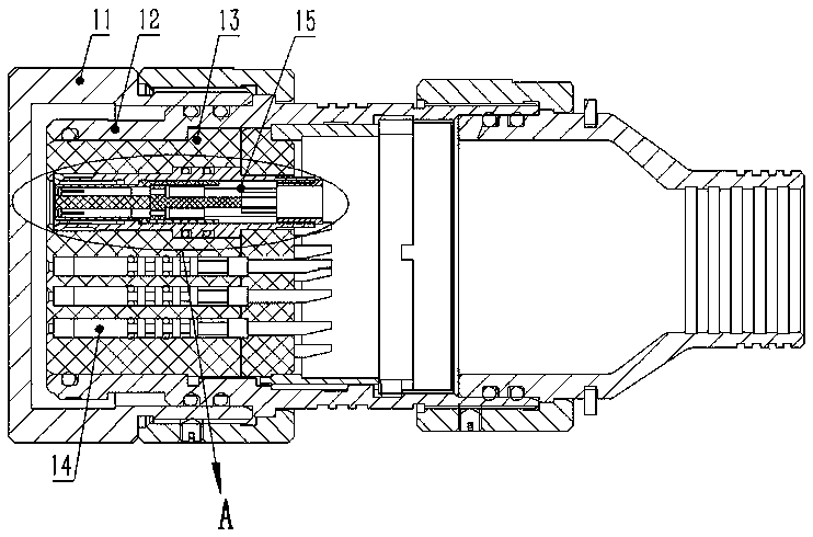
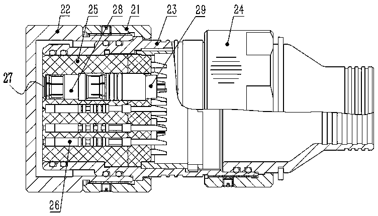
[0024] The embodiment of connector among the present invention: as Figure 3 to Figure 6 As shown, the connector is a plug-type differential connector, including a connecting nut 21, a sealing cover 22, a housing 23, a cable accessory 24, an insulator 25, a low-frequency contact 26 and a high-speed four-core differential contact part 27, Wherein the connecting nut 21 is connected between the casing 23 and the sealing cover 22, the rear end of the connecting nut 21 is set on the outer periphery of the casing 23, and the front end of the connecting nut 21 is screwed and set on the outer periphery of the sealing cover 22. O-rings are used between the sealing cover 22 and the housing 23, between the housing 23 and the insulator 25, between the insulator 25 and the low-frequency contact 26, and between the insulator 25 and the high-speed four-core differential contact part 27 Achieving a seal.

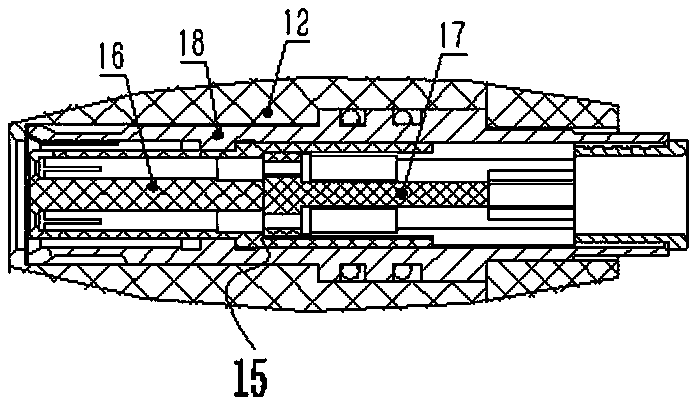
[0025] The high-speed four-core differential contact part 27 is composed of a transfer...


PUM


Abstract

The invention discloses a connector and a contact component thereof. The front contact member of the contact component is assembled in a front sleeve by adopting an insulator spacing and fixing mode, and the rear contact member is fixed in a rear sleeve in a spacing way by adopting a glass sintering sealing mode. Meanwhile, butt plugging of the front contact member and the contact member of another connector is realized, and conductive connection of a rear insulator and a conductive wire is realized so that a beryllium copper alloy or a tin bronze alloy can be adopted to act as the front contact member. Metal material suitable for glass sintering sealing is adopted to act as the rear contact member and the rear sleeve so that flowing and burning-resistant capacity of the plugging contact part of the contact members in the plugging process of the plug and the socket of the whole contact component can be guaranteed by the front contact member, and sealing performance between the contact members and the fixing sleeves of the contact component can be enhanced by glass sintering sealing as for the rear contact member. Therefore, sealing performance between the contact members and the fixing sleeves can be enhanced in the contact component under the premise of guaranteeing basic plugging and flowing performance.

Description

technical field [0001] The invention relates to a connector and its contact parts. Background technique [0002] At present, in the design of sealed connectors, the O-ring structure is usually used to achieve sealing, such as figure 1 As shown, O-rings are designed between the sealing cover 11 and the housing 12 , between the housing 12 and the insulator 13 , and between the insulator 13 and the low-frequency contact 14 to seal the matching gap. When the sealed connector needs to transmit high-speed signals, it is usually necessary to use high-speed four-core differential contact components 15, such as figure 2 shown. Due to the limitation of the structural size of each socket-type differential contact in the high-speed four-core differential contact part 15, O-rings cannot be used between the differential contact in the high-speed four-core differential contact part 15 and the front insulator 16 and the rear insulator 17 At the same time, since the fixed sleeve 18 and t...

Claims


Application Information

Patent Timeline
IPC IPC(8): H01R13/40H01R13/03
CPCH01R13/03H01R13/40
Inventor 苏雯
Owner CHINA AVIATION OPTICAL-ELECTRICAL TECH CO LTD
Why Eureka
Try Eureka