
Tie plate and rail fastening point
A technology of fixed points and backing plates, which is applied in the direction of tracks, fixed rails, roads, etc., can solve the problem of unusable backing plates, and achieve the effects of avoiding crack formation, reducing pressure, and reducing the risk of crack formation
- Summary
- Abstract
- Description
- Claims
- Application Information
AI Technical Summary
Problems solved by technology
Method used
Image

Examples
Embodiment Construction
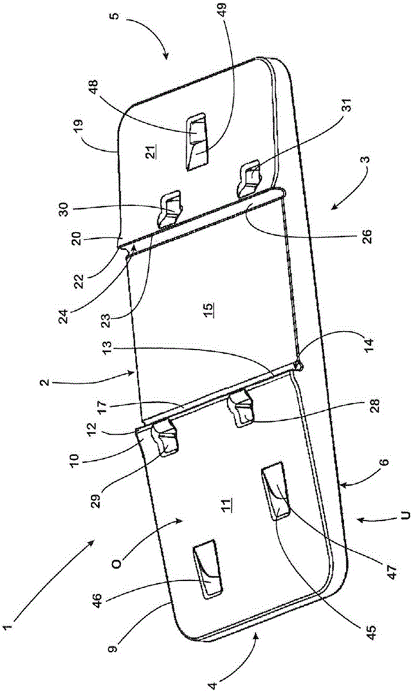
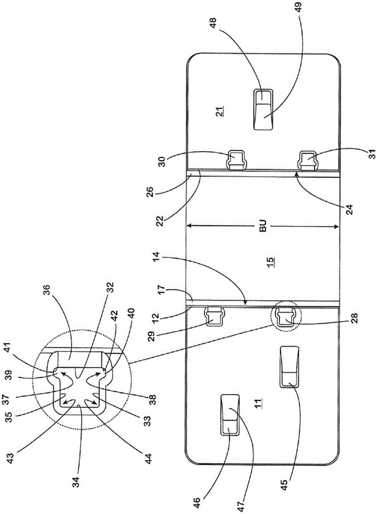
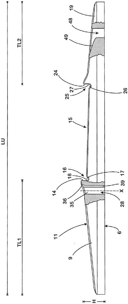
[0030] In a plan view, the backing plate 1 formed entirely by plastic, such as DIN abbreviated as PA6GF30 (30% glass fiber content) glass fiber reinforced polyamide plastic, has a rectangular, elongated basic shape: Long sides 2 , 3 running parallel to one another in longitudinal direction LU and two narrow sides 4 , 5 , also parallel to one another and transverse to long sides 2 , 3 , extend over width BU of backing plate 1 .
[0031] The backing plate 1 has a flat support surface 6 on the underside U, which rests in the mounting position with the support surface (attached Figure 4 ) stands on the flat support surface 8 arranged on the upper side of the crossties 7 .
[0032] Adjacent to the narrow side 4 , a first support section 9 is formed on the backing plate 1 , which has the full width BU of the backing plate 1 and a first partial length TL1 . On the upper side O opposite the lower side U of the base plate 1 , the support section 9 rises continuously like a roof surfa...
PUM
 Abstract
Description
Claims
Application Information