A spiral pipe production line

A production line and spiral pipe technology, applied in the field of new spiral pipe production lines, can solve the problems of long production cycle, cost reduction, and inability to accurately control the diameter and accuracy of steel pipes, and achieve the effect of liberating manpower and improving production efficiency

Inactive Publication Date: 2018-06-12
河北德威钢管有限公司
View PDF7 Cites 1 Cited by
  • Summary
  • Abstract
  • Description
  • Claims
  • Application Information

AI Technical Summary

Problems solved by technology

[0002] The pipelines used in daily life and buildings are generally cast pipes. The casting pipes are easy to manufacture and the production cycle is short, but the diameter of the cast pipes is too high to make large-diameter pipes. To solve this problem, there are currently strip steel coils The plate is the raw material, which is extruded at regular temperature by the forming machine and welded by the automatic double-sided submerged arc welding process to the spiral seam steel pipe. As far as casting pipes are concerned, the cost of a single steel pipe is greatly reduced and the adaptability is good, but the quality of the spiral steel pipes currently produced is low, mainly due to the following reasons: 1. Manual operation errors are large, and leakage welding is prone to occur; 2. , When connecting, manual docking, the accuracy is poor
3. The diameter accuracy of the steel pipe is low, and it is impossible to accurately control the diameter accuracy of the steel pipe; 4. The production cycle is long, and the full range of automatic control cannot be realized

Method used


Image

  • A spiral pipe production line
  • A spiral pipe production line
  • A spiral pipe production line

Examples


Embodiment Construction

[0040] The following is attached Figure 1-8, the present invention is further described:

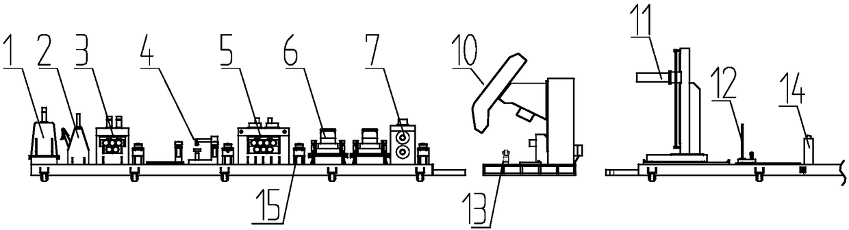
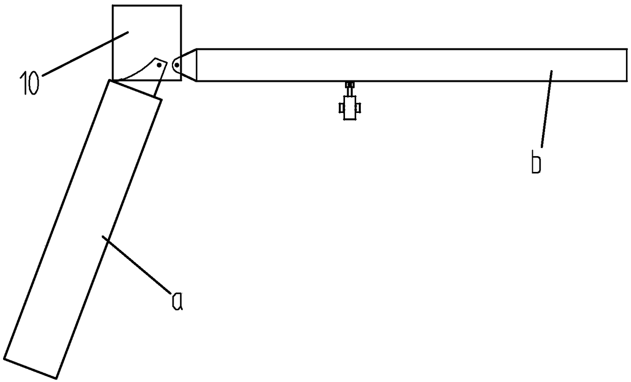
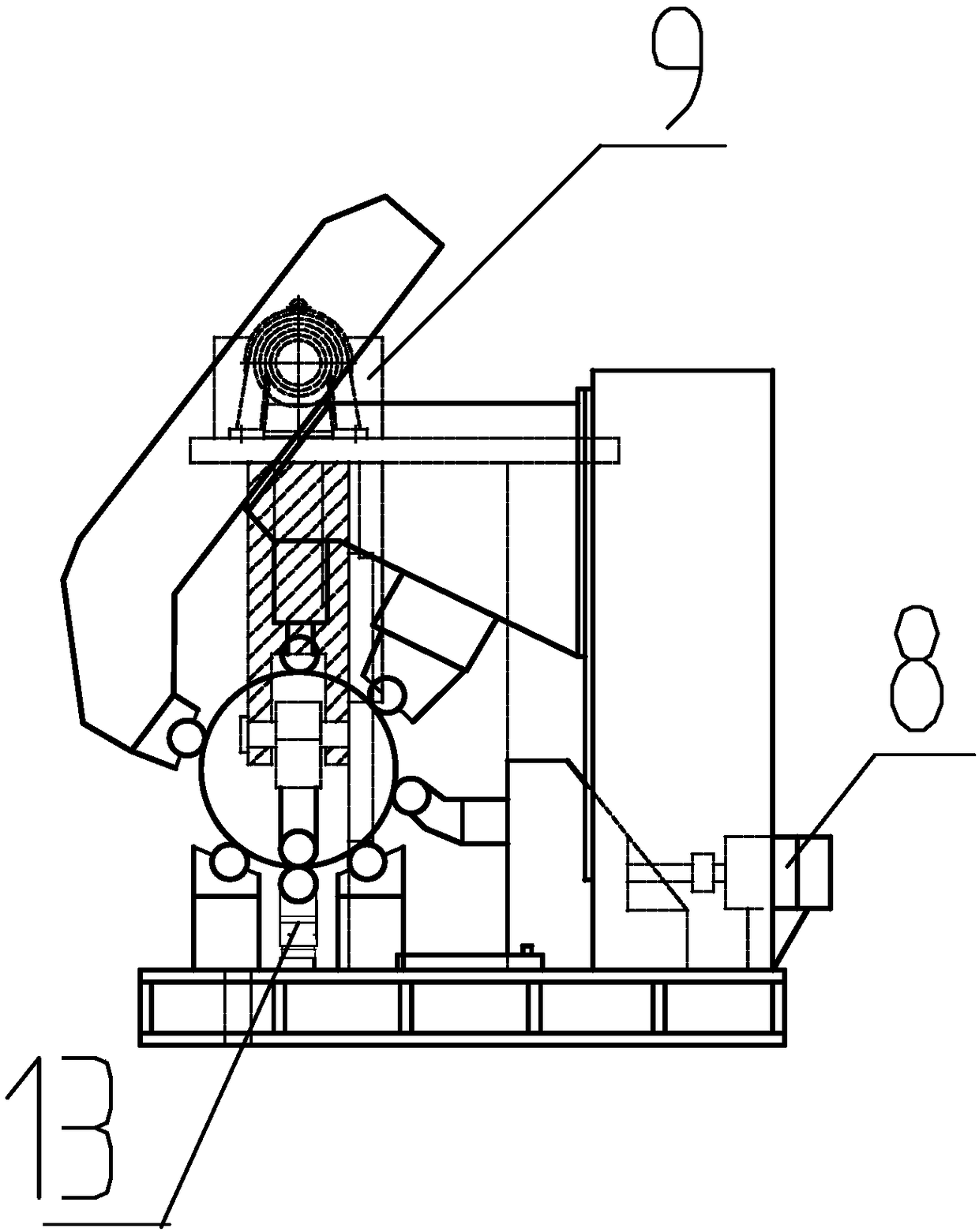
[0041] Such as figure 1 , figure 2 As shown, a novel spiral pipe production line is provided, which includes successively connected front axle forming frames a, molding equipment 10, and rear axle forming frames b, with clips between the front axle forming frames a and the rear axle forming frames b. horn;

[0042] On the front axle forming frame a, there are arranged in sequence,

[0043] The uncoiling device 1 is used to rotate and limit the coiled plate and also guide the coiled plate joint to the subsequent device;

[0044] The shovel head device 2 is used to preliminarily flatten the arc-shaped head of the coiled plate and transport it to subsequent equipment.

[0045] Coarse flattening device 3, used to flatten the coiled plate for the first time;

[0046] The quick docking device 4 is used to quickly dock the tail end of the preceding steel plate and the head end of the su...


PUM


Abstract

The invention provides a novel spiral pipe production line and belongs to the field of production of spiral pipes. The production line comprises a decoiling device, a shovel head device, a rough leveling device, a fast butt joint device, a fine leveling device, an edge milling device, a traction device, a centering device, a cutting device and a rear axle carrier roller. A molding device comprises a bottom plate, a molding frame, a first roller beam, a second roller beam, a third roller beam, a fourth roller beam, a fifth roller beam, a sixth roller beam, a seventh roller beam and a welding pad roller. A work area used for making steel pipes is reserved in the center of the molding frame. The seven roller beams are arranged in the work area of the molding frame. An included angle is formed between every two roller beams, and the roller beams are spirally arranged. An automatic roller beam vertical sliding device and an automatic roller beam horizontal moving device are further arranged on the bottom plate. The automatic roller beam vertical sliding device is connected with the roller beam right opposite to the welding pad roller. The automatic roller beam horizontal moving device is connected with the roller beam located on the center horizontal plane of the work area. According to the novel spiral pipe production line, the structure of the production line is greatly adjusted, arrangement of the devices is more reasonable, and the yield is higher.

Description

technical field [0001] The invention belongs to the field of spiral steel pipe production, in particular to a novel spiral pipe production line. Background technique [0002] The pipelines used in daily life and buildings are generally cast pipes. The casting pipes are easy to manufacture and the production cycle is short, but the diameter of the cast pipes is too high to make large-diameter pipes. To solve this problem, there are currently strip steel coils The plate is the raw material, which is extruded at regular temperature by the forming machine and welded by the automatic double-sided submerged arc welding process to the spiral seam steel pipe. As far as casting pipes are concerned, the cost of a single steel pipe is greatly reduced and the adaptability is good, but the quality of the spiral steel pipes currently produced is low, mainly due to the following reasons: 1. Manual operation errors are large, and leakage welding is prone to occur; 2. , When connecting, man...

Claims


Application Information

Patent Timeline
Patent Type & Authority Patents(China)
IPC IPC(8): B21C37/083B21C37/12
CPCB21C37/122B21C37/126
Inventor 李宁
Owner 河北德威钢管有限公司
Why Eureka
Try Eureka