Fuel injection valve

A fuel injection valve, fuel injection technology, applied in the direction of fuel injection device, low-pressure fuel injection, charging system, etc., to achieve the effect of suppressing change, design or design change easily

Inactive Publication Date: 2016-03-09
HITACHI ASTEMO LTD
View PDF6 Cites 5 Cited by
  • Summary
  • Abstract
  • Description
  • Claims
  • Application Information

AI Technical Summary

Problems solved by technology

Or, in a fuel injection valve designed to obtain desired atomization performance, it is not easy to change the cross-sectional area of ​​the lateral passage and the cross-sectional area of ​​the fuel injection hole in order to adjust the fuel flow rate.

Method used


Image

  • Fuel injection valve
  • Fuel injection valve
  • Fuel injection valve

Examples


Embodiment Construction

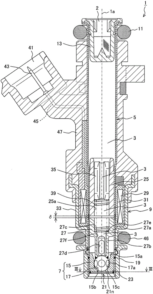
[0091] use Figure 1 to Figure 8 Examples of the present invention will be described.

[0092] use figure 1 The overall structure of the fuel injection valve 1 will be described. figure 1 It is a longitudinal sectional view showing a section along the central axis 1 a of the fuel injection valve 1 of the present embodiment. The central axis 1 a coincides with the axis (valve axis) of the mover 27 integrally provided with the valve body 17 described later, and coincides with the central axis of the cylindrical body 5 described later. In addition, the center axis line 1a also coincides with the center line of the valve seat 15b described later.

[0093] The fuel injection valve 1 is provided with a cylindrical body 5 made of a metal material extending from an upper end to a lower end. Inside the cylindrical body 5, the fuel flow path 3 is formed substantially along the central axis 1a. exist figure 1 In , the upper end portion (upper end side) is referred to as the base...


PUM


Abstract

The invention provides a fuel injection valve which comprises a rotary chamber and a horizental pessage, the fuel injection valve can restrain the variation of micronization performance and also can adjust the fuel flow ejected from a fuel injection hole. The fuel injection valve comprises the fuel injection hole (220), the rotary chamber (212) and the horizental pessage (211), wherein an inlet of the fuel injection hole (220) is arranged on the bottom of the rotary chamber (212), a side wall (211o) of the horizental pessage is separately connected with an upstream terminal (212cs) and a downstream terminal (212ce) of an inner circumference wall (212c) of the rotary chamber (212), under the condition of a first extending line (211ol) and a second extending line (211il) extending along the side wall (211o), on a flat projective plane vertical to the central axis of the fuel injection valve, a projection of an inlet opening (220i) of the fuel injection hole (220) exceeding a projection of the second extending line (211il) is arranged on a projection side of the side wall (211o) or a projection side of the first extending line (211ol).

Description

technical field [0001] The present invention relates to a fuel injection valve that generates swirl fuel upstream of a fuel injection hole and then injects swirl fuel from the fuel injection hole. Background technique [0002] A fuel injection valve described in Japanese Unexamined Patent Publication No. 2003-336562 (Patent Document 1) is known as background art in this technical field. In this fuel injection valve, a transverse passage communicating with a downstream end of the valve seat and a swirl chamber in which the downstream end of the transverse passage opens in a tangential direction is formed between the seat member and the injection plate joined to the front end surface of the seat member. , the fuel injection hole is drilled in the injection plate, and the fuel injection hole injects the fuel imparted with swirl by the swirl chamber. Distance (refer to the abstract of the instruction manual). In this fuel injection valve, atomization of the injected fuel is pr...

Claims


Application Information

Patent Timeline
Patent Type & Authority Applications(China)
IPC IPC(8): F02M61/18
CPCF02M61/162F02M61/163F02M69/044F02M61/1853
Inventor 长冈正树小林信章木下隆太
Owner HITACHI ASTEMO LTD
Why Eureka
Try Eureka