Reinforcing device for machining machinery base

A processing machine and reinforcement device technology, which is applied in the field of processing machine base reinforcement devices, can solve the problems that the base is easily damaged, easily tilted, and affects production efficiency, etc., and achieve the effects of enhanced support effect, effective support structure, and enhanced connection efficiency

Inactive Publication Date: 2016-03-09
重庆凯顺机械有限公司
View PDF6 Cites 1 Cited by
  • Summary
  • Abstract
  • Description
  • Claims
  • Application Information

AI Technical Summary

Problems solved by technology

[0002] A base is usually installed under the processing machine to support its structure. The existin

Method used


Image

  • Reinforcing device for machining machinery base

Examples


Embodiment 1

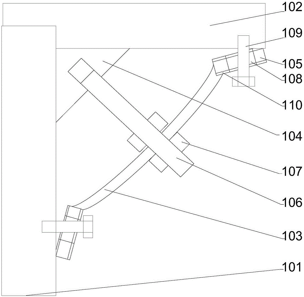
[0019] Such as figure 1 As shown, a processing machine base reinforcement device includes a base body 101 and a processing machine body 102 disposed above the base body 101, a support plate 103 is provided below the processing machine body 101, and the support plate 103 is Placed obliquely, the middle part of the support plate 103 is arched obliquely downward, a top angle part is formed between the base body 101 and the lower end surface of the processing machine body 102, and a pad is provided at the top foot part Block 104, the two right-angled sides of the pad 104 are attached to the lower end surface of the processing machine body 102 and the side wall of the base body 101 respectively, and the two ends of the support plate 103 are respectively A fixing plate 105 is provided, a through hole is provided in the middle of the support plate 103, a threaded hole is provided on the slope of the pad 104, and a stud 106 is provided in the through hole, and the One end of the stud...

Embodiment 2

[0023] This embodiment is based on Embodiment 1, in order to achieve a better fixing effect, in this embodiment, preferably, the end of the fixing plate 105 close to the supporting plate 103 points to the supporting plate 103 Central arch.

[0024] In order to achieve a better cushioning effect, in this embodiment, preferably, a rubber sheath 110 is fitted on the fixing plate 105 .

[0025] In order to enable the stud to better define the position and shape of the support plate, and at the same time enable the lock nut to better push the support plate, in this embodiment, preferably, two locks are arranged on the stud 106 Clamping nuts 107 , the two locking nuts 107 are respectively located on both sides of the support plate 103 . When adjusting, adjust the two lock nuts on the stud at the same time to realize the adjustment of the support plate.

[0026] In order to facilitate processing and make the structure more reliable, in this embodiment, preferably, the support plate...


PUM


Abstract

The invention discloses a reinforcing device for machining a machinery base. The reinforcing device comprises a base body and a machining machinery body, wherein the machining machinery body is arranged above the base body. A supporting plate is arranged below the machining machinery body and placed slantingly. The middle of the supporting plate hunches up towards the slanting underneath direction. A point angle part is formed between the base body and the lower end surface of the machining machinery body. A cushion block is arranged on the point angle part. The two right-angle sides of the cushion block are attached to the lower end surface of the machining machinery body and the side wall of the base body respectively. Fixing plates are arranged at the two ends of the supporting plate respectively. A through hole is formed in the middle of the supporting plate. A threaded hole is formed in the slanting face of the cushion block. A stud is arranged in the through hole. According to the reinforcing device for machining the machinery base, connecting and supporting of the base body and the machining machinery body are achieved through the supporting plate and the fixing plates arranged at the two ends of the supporting plate, the structure is simple, and operating is convenient.

Description

technical field [0001] The invention relates to a reinforcing device for a processing machine base. Background technique [0002] A base is usually installed under the processing machine to support its structure. The existing base has a simple structure and usually does not have a support reinforcement device. Productivity. Contents of the invention [0003] The purpose of the present invention is to provide a reinforcing device for the base of a processing machine, which can improve the problems in the prior art. By adopting a support plate and a fixed plate structure arranged at both ends of the support plate, the connection and support of the base body and the processing machine body are realized. Simple and easy to operate. [0004] The present invention is realized through the following technical solutions: [0005] A processing machine base reinforcement device, comprising a base body and a processing machine body arranged above the base body, a support plate is a...

Claims


Application Information

Patent Timeline
IPC IPC(8): F16M5/00
Inventor 万平
Owner 重庆凯顺机械有限公司
Why Eureka
Try Eureka