Traffic flow capacity increasing control method for comprehensive waiting area at road intersection

A control method and technology of waiting area, which are applied in the field of vehicle control at urban intersections, can solve the problems of insufficient utilization of intersection space resources, difficulty in meeting traffic demands, and waste of intersection space, etc. Storage capacity, ensuring traffic capacity and driving safety, and reducing the effect of lane saturation

Active Publication Date: 2016-03-09
SHANGHAI URBAN CONSTR DESIGN RES INST GRP CO LTD
View PDF6 Cites 24 Cited by
  • Summary
  • Abstract
  • Description
  • Claims
  • Application Information

AI Technical Summary

Problems solved by technology

Therefore, the intersection congestion is serious, and the existing traffic capacity is difficult to meet the traffic demand
[0008] 2. There is a waste of space at intersections
When passing through vehicles,

Method used


Image

  • Traffic flow capacity increasing control method for comprehensive waiting area at road intersection
  • Traffic flow capacity increasing control method for comprehensive waiting area at road intersection
  • Traffic flow capacity increasing control method for comprehensive waiting area at road intersection

Examples


Example Embodiment

[0056] Example 1

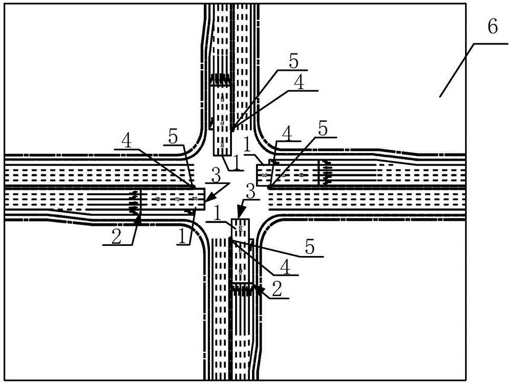
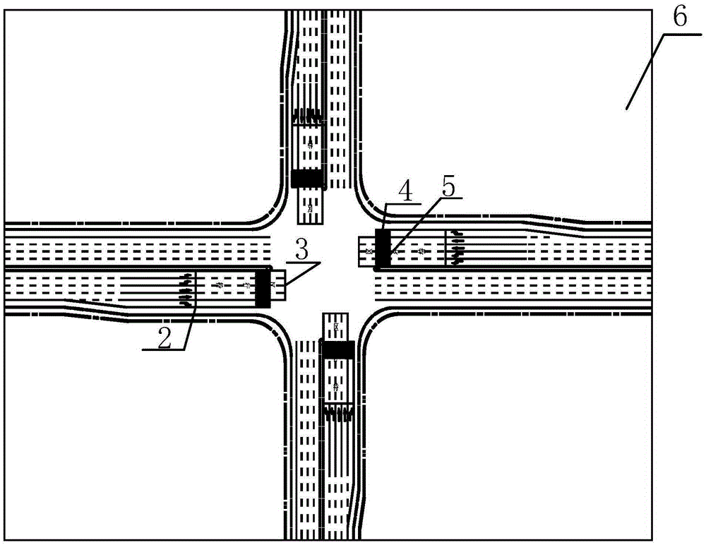
[0057] The purpose of the present invention is achieved through the following technical solutions: Figure 2 ~ Figure 4 As shown, the method for controlling the increase in traffic volume in the integrated waiting area at a road intersection provided in this embodiment includes the following steps:

[0058] S1. Add comprehensive waiting area 1 and parking line

[0059] Add a comprehensive waiting area 1 in front of the straight and left-turn lanes (a shared waiting area for straight and left turns), and add a stop line 2 at the end of the waiting area to control the parking of straight or left-turning vehicles in the integrated waiting area.

[0060] Add secondary stop line 3. Such as Figure 2 ~ Figure 4 As shown, taking the west entrance as an example, the extension of the secondary parking line 3 is located along the stone edge line of the north-south entrance road (that is, the extension line of the second parking line at the west entrance coincides with the sto...

Example

[0096] Effect comparison example 2

[0097] Take a certain intersection in a city as an example, suppose that the straight traffic at the west entrance of the intersection is 1000pcu / h, the left turn traffic is 700pcu / h, the signal cycle of the intersection is 210s, and the green signal ratio of a single phase is 0.25. According to formula 7 of the present invention, the length of the comprehensive waiting area L=68m can be calculated. In a straight or left-turning lane, there are about 20 cars in a line in one phase. In this way, by increasing the length of the comprehensive waiting area of ​​68m, about 10 cars can be stored, which improves the storage capacity of the road by 50%.

[0098] In contrast, in terms of capacity, the current intersection capacity is 12,696pcu / h, and the four entrances with this method are equipped with comprehensive waiting areas, which are one cycle and one direction to go straight and turn left, and a total of 40 vehicles will pass through. Standard ...


PUM


Abstract

The invention discloses a traffic flow capacity increasing control method for a comprehensive waiting area at a road intersection, comprising the following steps: S1, adding a comprehensive waiting area, setting a primary stopping line and a secondary stopping line at the end of the comprehensive waiting area, and setting the distance between the primary stopping line and the secondary stopping line as the length of the comprehensive waiting area; and S2, adding a variable information board, pre-signal lamps and an induction coil buried under the road surface to the medial strip of the road opposite the comprehensive waiting area, wherein the pre-signal lamps include a pre-signal red lamp and a pre-signal green lamp, and the pre-signal red lamp goes on 10-12 seconds earlier than an original go-straight or turn-left traffic signal green lamp at the intersection. By adopting the method of the invention, the traffic capacity of the intersection is improved greatly, and the space resources of the intersection are prevented from lying idle.

Description

technical field [0001] The invention relates to a vehicle control method at an urban intersection, in particular to a method for controlling traffic volume increase in a comprehensive waiting area of ​​a road intersection. Background technique [0002] In urban roads, the one-way 4-lane road at the intersection is generally channelized into 5 entrance lanes, 2 left-turn lanes, 2 through lanes, and 1 right-turn lane, usually with a left-turn waiting area, such as figure 1 shown. "Ten" intersections generally adopt four-phase signal control. [0003] Phase one is going straight from north to south, turning left from north to south and entering the left-turn waiting area; phase two is turning left from north to south; phase three is going straight from east to west, turning left from east to west and entering the left-turn waiting area; phase four is turning left from east to west. Therefore, the current situation of traffic flow channelization at road intersections has the f...

Claims


Application Information

Patent Timeline
IPC IPC(8): G08G1/00
CPCG08G1/00
Inventor 刘伟杰彭庆艳吴金龙吴国荣
Owner SHANGHAI URBAN CONSTR DESIGN RES INST GRP CO LTD
Why Eureka
Try Eureka