
Liquid crystal display device

A liquid crystal display device and liquid crystal panel technology, applied in static indicators, instruments, etc., can solve problems such as screen flicker and mutual interference, and achieve the effects of power consumption, less power, and improved screen flicker and mutual interference.

Active Publication Date: 2016-03-09
WUHAN CHINA STAR OPTOELECTRONICS TECH CO LTD
View PDF6 Cites 6 Cited by
  • Summary
  • Abstract
  • Description
  • Claims
  • Application Information

AI Technical Summary

Problems solved by technology

[0005] The object of the present invention is to provide a liquid crystal display device, which can solve the problems of screen flicker and mutual interference in the prior art

Method used


Image

  • Liquid crystal display device
  • Liquid crystal display device
  • Liquid crystal display device

Examples


Embodiment Construction

[0028] The following descriptions of the various embodiments refer to the accompanying drawings to illustrate specific embodiments in which the present invention can be practiced.

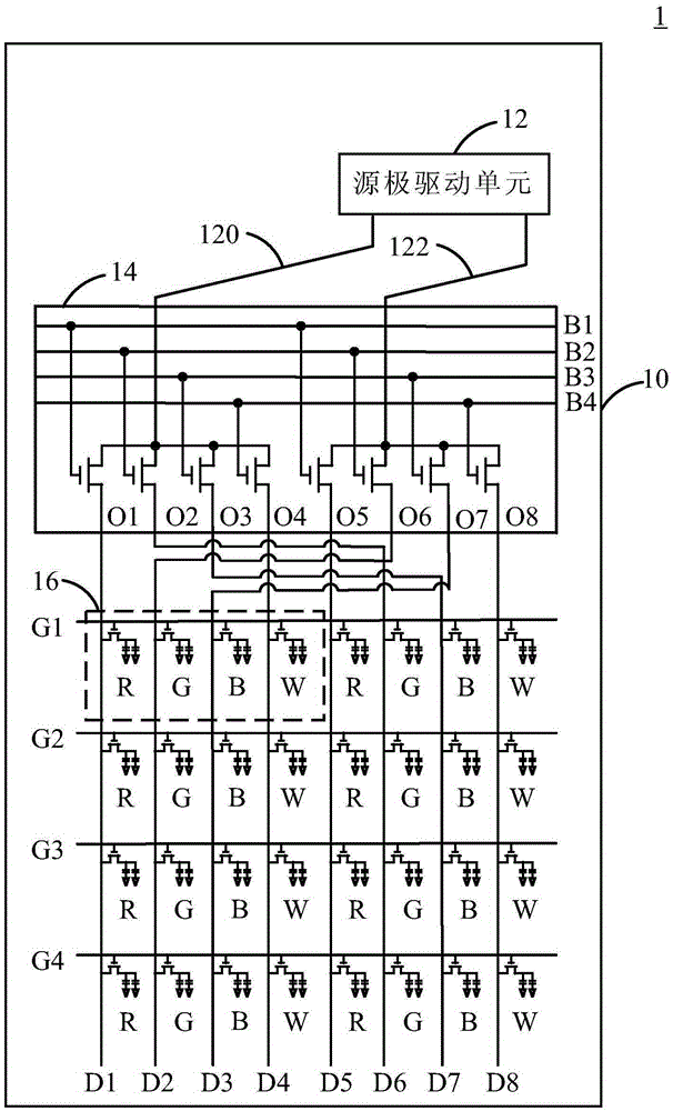
[0029] see figure 1 , figure 1 It is a liquid crystal display device 1 according to an embodiment of the present invention.

[0030] The liquid crystal display device 1 includes a liquid crystal panel 10, at least one source drive unit 12 (one source drive unit 12 is shown in the figure), at least one splitter 14 (one splitter 14 is shown in the figure), several A pixel unit 16, several scanning lines G1-G4 and several data lines D1-D8.

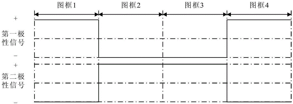
[0031] The source driver unit 12 is arranged on the liquid crystal panel 10 and includes at least one first fan-out line 120 and at least one second fan-out line 122 arranged alternately (the figure shows a first fan-out line 120 and a second fan-out line 122), the first fan-out line 120 is used to output a first polarity signal, and the second fan-out line 122...


PUM


Abstract

The invention provides a liquid crystal display device which comprises a liquid crystal panel; at least one source electrode driving unit which comprises at least one first fan-out line and at least one second fan-out line, which are arranged alternatively; at least one demultiplexer, which is electrically coupled to the first fan-out line and the second fan-out line and comprises a plurality of buses, a plurality of first output lines and a plurality of second output lines; and a plurality of picture element units, wherein each picture element unit comprises four sub-picture elements. The liquid crystal display device can solve the problems of picture flickering and crosstalk in the prior art.

Description

technical field [0001] The invention relates to a display device, in particular to a liquid crystal display device. Background technique [0002] In the existing liquid crystal display device with red, green, blue and white (RGBW) pixel structure, in order to reduce the number of pins (pins) of the source integrated circuit (SourceIntegratedCircuit; SourceIC), a splitter (Demultiplexer; DE-Mux) is usually used. ) divides one of the fan-outlines of the source integrated chip into multiple output lines, the splitter then controls the conduction and non-conduction of each output line, and finally according to the conduction and non-conduction of each output line and scanning The conduction and non-conduction of the lines write the data to be written into the pixels of the display area through the data lines. [0003] However, the above control method will cause multiple output lines corresponding to the same fan-out line to be driven with the same polarity, so that the liquid ...

Claims


Application Information

Patent Timeline
Patent Type & Authority Applications(China)
IPC IPC(8): G09G3/36
CPCG09G3/3614G09G3/3607G09G3/3685G09G2300/0426G09G2300/0452G09G2310/0227G09G2310/0297G09G2320/0209G09G2320/0247
Inventor 王聪杜鹏
Owner WUHAN CHINA STAR OPTOELECTRONICS TECH CO LTD
Learn More