Liquid heat dissipation structure for motor controller

A technology of motor controller and heat dissipation structure, which is applied to the structural parts of electrical equipment, electrical components, cooling/ventilation/heating transformation, etc., to achieve the effect of accelerating heat loss and improving sealing

Inactive Publication Date: 2016-03-09
WISDRI WUHAN AUTOMATION
View PDF12 Cites 14 Cited by
  • Summary
  • Abstract
  • Description
  • Claims
  • Application Information

AI Technical Summary

Problems solved by technology

However, the demand for many power modules with increasing energy consumption and p

Method used


Image

  • Liquid heat dissipation structure for motor controller
  • Liquid heat dissipation structure for motor controller
  • Liquid heat dissipation structure for motor controller

Examples


Embodiment Construction

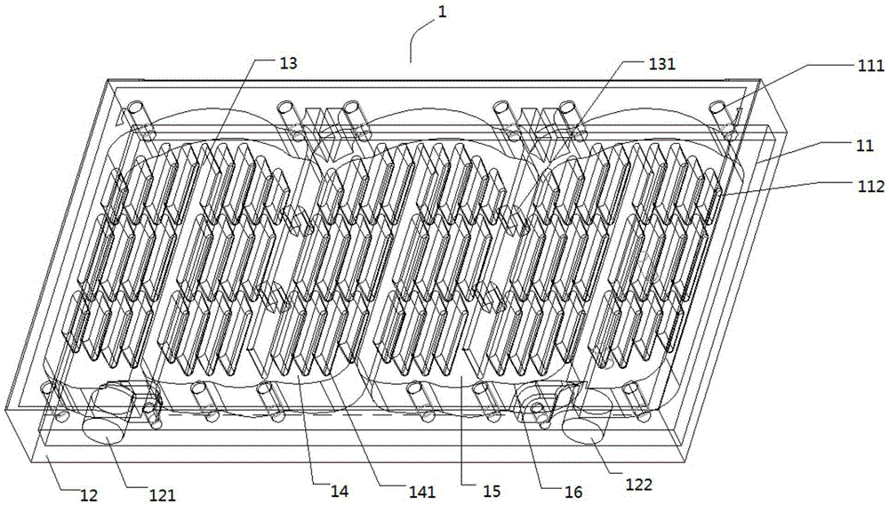
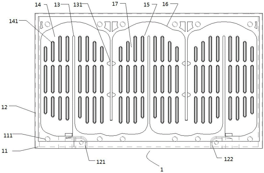
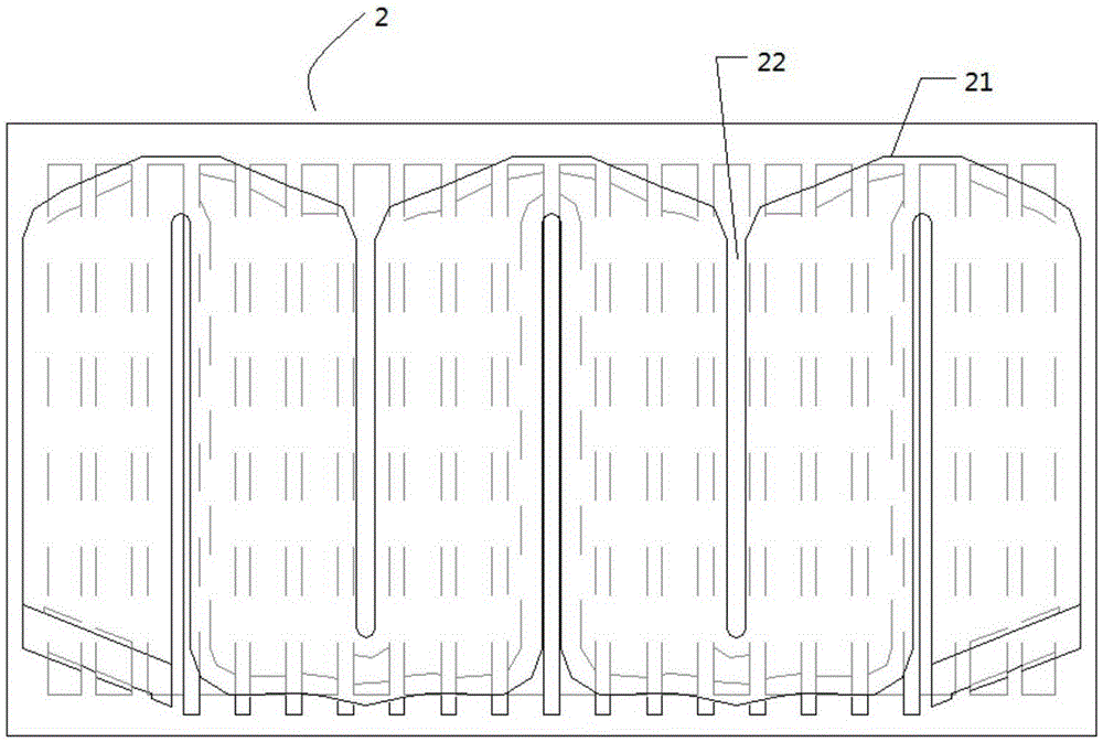
[0020] according to Figure 1 to Figure 2 Shown: a liquid heat dissipation structure of a motor controller, including a heat dissipation plate main body 1 and a cover plate 2 arranged parallel to the heat dissipation plate main body 1; the other side of the heat dissipation plate main body 1 is used to fix the power module unit, and then The heat generated during the working process of the power module unit is taken away through the liquid in the liquid heat dissipation structure, so as to achieve the purpose of heat dissipation, so as to speed up the heat dissipation efficiency of the power module unit and improve the service life.

[0021] Preferably, the heat dissipation plate main body 1 includes: a heat dissipation substrate 11, a side plate 12 with a liquid inlet 121 and a liquid outlet 122, a plurality of baffles 13, a plurality of guide fin groups 14, and the heat dissipation substrate 11 The side plate 12 enclosing a semi-closed accommodating cavity 15 is perpendicula...


PUM


Abstract

A liquid heat dissipation structure for a motor controller comprises a heat dissipation plate main body and a cover plate arranged in parallel with the heat dissipation plate main body; wherein the heat dissipation plate main body comprises a heat dissipation substrate, a side plate with a liquid inlet and a liquid outlet, a plurality of flow baffles, and a plurality of diversion fin groups; the side plate is perpendicular to the heat dissipation substrate, a semi-closure containing cavity is enclosed by the side plate and the heat dissipation substrate; and the flow baffles and the diversion fin groups are arranged in the containing cavity. The liquid heat dissipation structure has the advantages that: with the design of at least two S-shaped main flow channels connected in series and the diversion fin groups, a flow diversion function is provided, and at the same time, dissipation of the heat in the motor controller is effectively accelerated; with the design of S-shaped bosses, which are in seamless connection with the S-shaped main flow channels on the heat dissipation substrate, on the cover plate, closure of the motor controller is improved, and at the same time, liquid having the heat dissipation effect can flow orderly between the main flow channels and secondary flow channels, so as to achieve the purpose of liquid heat dissipation.

Description

technical field [0001] The invention relates to the technical field of heat dissipation, in particular to a liquid heat dissipation structure of a motor controller. Background technique [0002] With the rapid development of modern power technology, the market share of motor controllers for new energy electric vehicles is getting higher and higher. Due to the space limitation of the vehicle, the volume of the motor controller is gradually reduced, while the power density of the motor controller is increasing year by year. Therefore, the heat dissipation efficiency of its internal power devices or units plays an important role. At this stage, forced air cooling is used as a heat dissipation method, which cannot meet the heat dissipation requirements of high power density, and is limited by the volume of the space structure. [0003] At present, most of the water-cooled plates on the market adopt the structure of aluminum plate and copper tube, that is, the copper tube is ben...

Claims


Application Information

Patent Timeline
IPC IPC(8): H05K7/20
CPCH05K7/20254
Inventor 王涛昝向东康现伟王国强王胜勇
Owner WISDRI WUHAN AUTOMATION
Why Eureka
Try Eureka