Screw compressor
A screw compressor and screw technology, which is used in mechanical equipment, machines/engines, liquid fuel engines, etc., can solve the problems of reduced reliability, increased reliability, and high refrigerant temperature of single-screw compressors, and achieves high reliability, restraint Contact and sintering, the effect of suppressing thermal expansion
- Summary
- Abstract
- Description
- Claims
- Application Information
AI Technical Summary
Problems solved by technology
Method used
Image
Examples
Embodiment approach 1
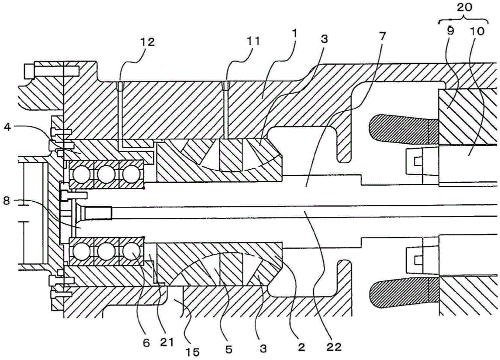
[0028] figure 1 It is a schematic configuration diagram of the screw compressor according to Embodiment 1 of the present invention.
[0029] Hereinafter, the configuration of the screw compressor according to Embodiment 1 will be described.
[0030] The screw compressor involved in Embodiment 1 is a single screw compressor, such as figure 1 As shown, a cylindrical casing 1 , a screw rotor 2 housed in the casing 1 , a star wheel 3 , a motor 20 , and a bearing support 4 are provided.
[0031] The outer peripheral portion of the screw rotor 2 is formed with a plurality of helical screw grooves 5, and the screw rotor 2 is arranged on the discharge side of the casing 1 ( figure 1 to the left of the ).
[0032] The motor 20 is composed of a stator 9 internally connected and fixed to the casing 1 and a motor rotor 10 arranged inside the stator 9, and drives the screw rotor 2 connected via the screw shaft 7 to rotate. In the case of an inverter system, the motor 20 speed is con...
Embodiment approach 2
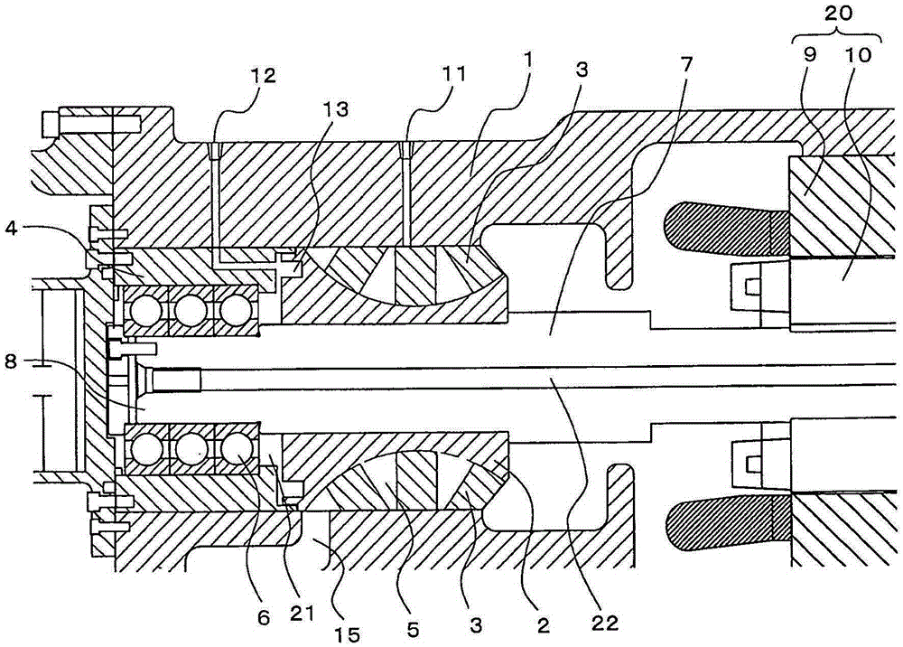
[0048] figure 2 It is a schematic configuration diagram of a screw compressor according to Embodiment 2 of the present invention.
[0049] Hereinafter, Embodiment 2 will be described, but the content overlapping with Embodiment 1 will be omitted, and the same parts as Embodiment 1 or corresponding parts will be given the same reference numerals.
[0050] In the single screw compressor according to Embodiment 2, grooves 13 are formed in the screw rotor 2 at portions receiving oil or liquid refrigerant sprayed from the second flow path 12 formed in the bearing support portion 4 .
[0051] Forming the grooves 13 reduces the heat capacity of the screw rotor 2 and increases the surface area of the screw rotor 2 that receives oil or liquid refrigerant sprayed from the second flow path 12 formed in the bearing support portion 4 . Therefore, the thermal expansion of the screw rotor 2 can be suppressed further than in the first embodiment. In addition, the grooves 13 are formed to...
Embodiment approach 3
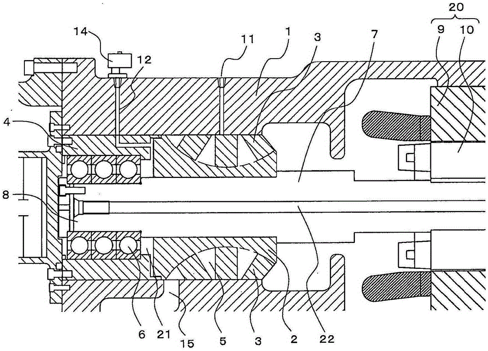
[0055] image 3 It is a schematic configuration diagram of a screw compressor according to Embodiment 3 of the present invention.
[0056] Hereinafter, Embodiment 3 will be described, but the content overlapping with Embodiment 1 will be omitted, and the same parts as Embodiment 1 or corresponding parts will be assigned the same reference numerals.
[0057] In the single-screw compressor according to Embodiment 3, a valve 14 capable of being opened and closed is provided on the inlet side (casing 1 side) of the second flow path 12 .
[0058] By providing the valve 14, the valve 14 is opened only when the temperature of the gas refrigerant compressed in the compression chamber rises (for example, when the temperature of the gas refrigerant compressed in the compression chamber rises compared with a specified temperature) to allow the oil or liquid to refrigerate. The agent flows to the second flow path 12 and is sprayed toward the screw rotor 2 . Then, the screw rotor 2 recei...
PUM
 Abstract
Description
Claims
Application Information
 - R&D
- Intellectual Property
- Life Sciences
- Materials
- Tech Scout
- Unparalleled Data Quality
- Higher Quality Content
- 60% Fewer Hallucinations
Browse by: Latest US Patents, China's latest patents, Technical Efficacy Thesaurus, Application Domain, Technology Topic, Popular Technical Reports.
© 2025 PatSnap. All rights reserved.Legal|Privacy policy|Modern Slavery Act Transparency Statement|Sitemap|About US| Contact US: help@patsnap.com


