Supercharge Your Innovation With Domain-Expert AI Agents!

Tube bending machine

A pipe bending machine and fuselage technology, which is applied in the field of pipe bending machines, can solve problems such as high cost, high labor intensity, and unstable quality, and achieve the effects of low cost, stable transmission, and improved work efficiency

Inactive Publication Date: 2016-03-16
浙江万盾制冷股份有限公司
View PDF0 Cites 0 Cited by
  • Summary
  • Abstract
  • Description
  • Claims
  • Application Information

AI Technical Summary

Problems solved by technology

[0002] With the rapid development of economy and technology, mechanical automation has also achieved rapid development. The current pipe bending mainly relies on manual operation, which is labor-intensive, unstable in quality, and high in cost.

Method used


Image

  • Tube bending machine
  • Tube bending machine

Examples


Embodiment Construction

[0011] In order to deepen the understanding of the present invention, the present invention will be further described below in conjunction with examples, which are only used to explain the present invention and do not constitute a limitation to the protection scope of the present invention.

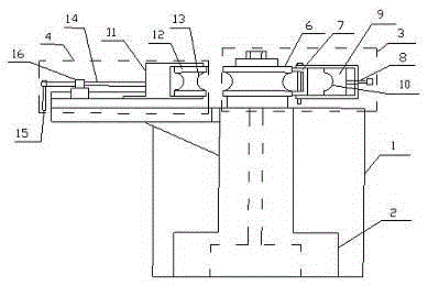
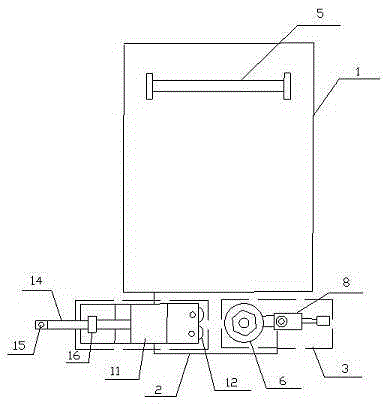
[0012] A pipe bending machine as shown in the figure includes a fuselage 1, a fixed seat 2, a turntable 3, a movable workbench 4 and a support frame 5, and the lower side wall at one end of the fuselage 1 is connected with a fixed seat 2 , the turntable 3 and the movable workbench 4 are fixed on the fixed seat 2, and the upper surface of the other end of the fuselage 1 is connected with a support frame 5, and the turntable 3 and the movable workbench 4 are placed on a straight line.

[0013] The turntable 3 includes a disk 6, the outer circumference of the disk 6 is connected to a pull rod 8 with an opening at one end through a connecting piece 7, a movable block 9 is arranged in the openi...


PUM


Abstract

The invention relates to a tube bending machine which comprises a machine body, a fixed seat, a rotary table, a movable workbench and a supporting frame, wherein the fixed base is connected on the side wall of the lower part at one end of the machine body; the rotary table and the movable workbench are respectively arranged at left and right sides of the fixed base; the upper surface of the other end of the machine body is connected with the supporting frame; a slide groove which is matched with the movable workbench is formed in the fixed base; the movable workbench is connected with the groove in the fixed base through a lug boss on the bottom surface in a matched mode; a clamping device for fixing the movable workbench is arranged on the movable workbench; the rotary table comprises a circular disc; the outer circumference of the circular disc is connected with a drawbar with an opening in one end through a connector; and a movable block is arranged in the opening of the drawbar; and one end, close to the connector, of the movable block is provided with a first arc-shaped slot. The tube bending machine has the beneficial effects that: transmission in work is relatively stable, bending is relatively convenient, cost is relatively low and working efficiency is greatly improved.

Description

technical field [0001] The invention belongs to the technical field of air-conditioning pipe processing, and in particular relates to a pipe bending machine. Background technique [0002] With the rapid development of economy and technology, mechanical automation has also achieved rapid development. The current pipe bending mainly relies on manual operation, which is labor-intensive, unstable in quality, and high in cost. Contents of the invention [0003] In view of the problems existing in the prior art, the object of the present invention is to design and provide a technical solution for a pipe bending machine. [0004] The pipe bending machine described above is characterized in that it includes a fuselage, a fixed seat, a turntable, a movable workbench and a support frame, and the lower side wall at one end of the fuselage is connected with a fixed seat, a turntable and a movable The workbench is arranged on the left and right sides of the fixed seat respectively, an...

Claims


Application Information

Patent Timeline
Patent Type & Authority Applications(China)
IPC IPC(8): B21D7/04
CPCB21D7/04
Inventor 万胜亨
Owner 浙江万盾制冷股份有限公司
Features
  • R&D
  • Intellectual Property
  • Life Sciences
  • Materials
  • Tech Scout
  • Unparalleled Data Quality
  • Higher Quality Content
  • 60% Fewer Hallucinations
Learn More