Sliding plate bending die

A bending die and sliding plate technology, applied in metal processing equipment, forming tools, manufacturing tools, etc., can solve the problems of complex operation, low processing efficiency and high processing cost, and achieve the effect of simple operation and improved efficiency.

Inactive Publication Date: 2016-03-16
CHONGQING WANSI METAL SPECIAL TYPE FORMING
View PDF0 Cites 2 Cited by
  • Summary
  • Abstract
  • Description
  • Claims
  • Application Information

AI Technical Summary

Problems solved by technology

like figure 2 As shown, there is a kind of curved piece whose tail ends are parallel and close together, and whose head is bent into a circle. At present, the processing method of this kind of curved piece is to process the curved piece into a U-shaped piece first, and then fix the non-open end of the U-shaped piece. , using another stamping device to stamp the two legs at the opening end to make them close together to form the final product. This molding method requires the use of two sets of equipment, which has high processing costs, complicated operations, and low processing efficiency.

Method used


Image

  • Sliding plate bending die
  • Sliding plate bending die

Examples


Embodiment Construction

[0012] The present invention will be described in further detail below by means of specific embodiments:

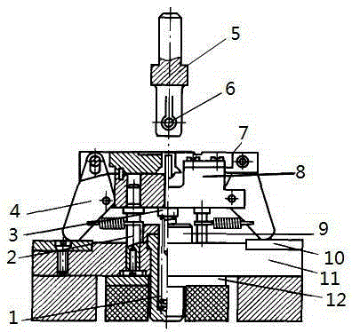
[0013] The reference signs in the drawings of the description include: compression spring 1, guide post 2, ejector rod 3, pendulum block 4, punch support 5, mandrel punch 6, forming slide block 7, die base frame 8, limit block 9. The first backing plate 10 , the base 11 , and the second backing plate 12 .

[0014] The embodiment is basically as attached figure 1 Shown: the skateboard bending die of this embodiment, the base 11 is placed on the upper part of the two supports, a rubber washer is arranged between the two supports, and a second backing plate 12 is arranged on the upper part of the rubber washer, and the second backing plate 12 is supported on The lower part of the base 11. A guide seat is installed on the rubber gasket and the second backing plate 12, a vertically movable push rod 3 is arranged in the guide seat, a flange is provided on the top of the push...


PUM


Abstract

The invention discloses a sliding plate bending die which is specially used for integrally forming the head of a bent part into a circular shape and enabling two supporting legs at the tail end to abut against each other tightly. The sliding plate bending die comprises a base, wherein two guiding columns are symmetrically arranged on the base; a concave die seat frame which can move along a guiding column vertically is arranged on each of the guiding columns; the outer end of each concave die seat frame is hinged with the middle portion of a swaying block; the sliding plate bending die further comprises two forming sliding blocks which are arranged horizontally and can slide relatively; the upper portion of each swaying block is hinged with the outer end of a corresponding forming sliding block; and a horizontal mandrel terrace die which can move vertically is arranged above a forming portion between the two forming sliding blocks.

Description

technical field [0001] The invention relates to a skateboard bending die. Background technique [0002] Bending molds are usually used for forming curved parts. There are many types of curved parts, such as U-shaped parts, round parts and hat-shaped parts. Such as figure 2 As shown, there is a kind of curved piece whose tail ends are parallel and close together, and whose head is bent into a circle. At present, the processing method of this kind of curved piece is to process the curved piece into a U-shaped piece first, and then fix the non-open end of the U-shaped piece. , using another stamping device to stamp the two legs at the opening end to make them close together to form the final product. This molding method needs to use two sets of equipment, the processing cost is high, the operation is complicated, and the processing efficiency is low. Contents of the invention [0003] The present invention intends to provide a skateboard bending die specially used for one-t...

Claims


Application Information

Patent Timeline
Patent Type & Authority Applications(China)
IPC IPC(8): B21D37/10
CPCB21D37/10
Inventor 谷毅
Owner CHONGQING WANSI METAL SPECIAL TYPE FORMING
Why Eureka
Try Eureka