Multi-axis quick-change drill bit assembly structure and quick-change method for drilling holes in conveyor belts

A technology of assembly structure and drill bit replacement, applied in boring/drilling, drilling/drilling equipment, large fixed members, etc., to achieve the effects of improving processing efficiency, convenient installation and adjustment, and reliable positioning

Active Publication Date: 2018-03-09
镇江三维输送装备股份有限公司(中外合资)
View PDF8 Cites 0 Cited by
  • Summary
  • Abstract
  • Description
  • Claims
  • Application Information

AI Technical Summary

Problems solved by technology

[0003] The purpose of the present invention is to solve the problems in the processing of through holes on the existing conveyor belt, and propose a multi-axis quick-change drill assembly structure and Its quick change method can process multiple axes at the same time, and can move and adjust the position of the drill bit. The drill spindle can be quickly changed and installed, and the positioning is reliable and accurate.

Method used


Image

  • Multi-axis quick-change drill bit assembly structure and quick-change method for drilling holes in conveyor belts
  • Multi-axis quick-change drill bit assembly structure and quick-change method for drilling holes in conveyor belts
  • Multi-axis quick-change drill bit assembly structure and quick-change method for drilling holes in conveyor belts

Examples


Embodiment Construction

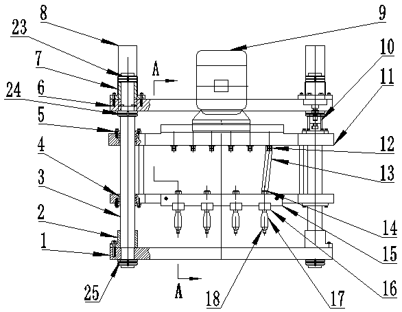
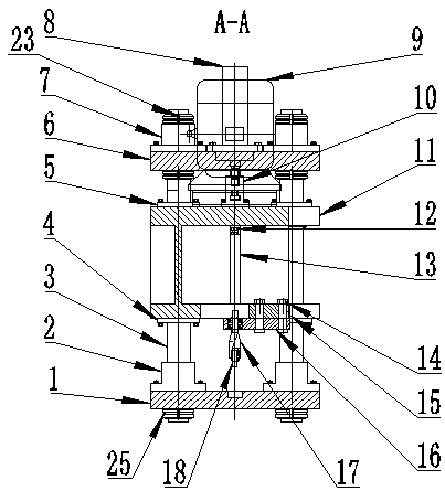
[0018] Such as figure 1 , figure 2 As shown, the present invention includes an upper base plate 6 and a lower base plate 1, the upper base plate 6 and the lower base plate 1 are arranged horizontally and parallel to each other, and vertical guide posts 3 are connected between the upper base plate 6 and the lower base plate 1, and the guide posts 3 have Four, a guide post 3 is arranged at the four corners of the upper base plate 6 and the lower base plate 1 respectively, and the guide post 3, the lower base plate 1 and the upper base plate 6 form a basic frame.

[0019] The lower end of each guide post 3 is fixedly covered with a guide sleeve 2, and the guide sleeve 2 forms a fixed connection with the lower base plate 1, so that the lower end of the guide post 3 and the lower base plate 1 are fixed, and the lower end of the guide post 3 is connected with a round nut 25, and the round nut 25 is located below the lower bottom plate 1, and the lower end of the guide post 3 is li...


PUM


Abstract

The invention discloses a multi-shaft quick replacing drill bit assembly structure for punching a conveyor belt and a quick replacing method. A spindle box is arranged between an upper bottom board and a lower bottom board and can move up and down along a guide column. An oil cylinder joint of a hydraulic oil cylinder is fixedly connected to the upper end of the spindle box, so that the spindle box is driven to move up and down. A motor is arranged above the outer portion of the spindle box, an output shaft of the motor is perpendicularly downward and is fixedly connected with the upper ends of output shafts of the spindle box, the lower end of each output shaft of the spindle box is connected with the upper end of a drill bit spindle through a cross universal joint, the lower end of each drill bit spindle is connected with a drill bit, the upper end of each drill bit spindle is connected with a drill bit support, the drill bit support is fixedly connected to the bottom of the spindle box through guide screws, and a limiting clamping board is arranged on the front side of the drill bit support. Multiple rectangular grooves correspondingly matched with the drill bit support are formed in the lower end of the limiting clamping board at intervals. The machined hole distance can be adjusted according to the requirements and the requirements for machining holes of various distances and distance arranging holes can be met.

Description

technical field [0001] The invention relates to a tool for processing through holes for various conveyor belts, in particular to a drill assembly structure specially used for drilling holes in conveyor belts. Background technique [0002] For the bucket elevator used in the grain industry, the lifting belt and the conveyor belt are important conveying parts. Generally, scrapers, buckets and other accessories are installed on the surface of the lifting belt and the conveyor belt, so it is necessary to process on the lifting belt and the conveyor belt. Accessory installation through holes for various specifications of row spacing and bucket spacing. At present, these mounting through holes are all processed on a punching machine and formed by punching. However, since the inside of products such as lifting belts and conveyor belts is an integral fabric core layer, the quality is soft and the elongation is relatively large, so when the through holes are stamped and installed, t...

Claims


Application Information

Patent Timeline
Patent Type & Authority Patents(China)
IPC IPC(8): B23B39/18B23B41/00B23Q1/25
CPCB23B39/161B23B39/18B23B41/00B23Q1/25
Inventor 李光千
Owner 镇江三维输送装备股份有限公司(中外合资)
Why Eureka
Try Eureka