A Worm Processing Mechanism with Reduced Weight

A processing mechanism and weight reduction technology, applied in the direction of worms, mechanical equipment, components with teeth, etc., can solve the problems of reducing costs and improving processing speed and precision, difficult to ensure the shape and position accuracy of tooth grooves, and low transmission efficiency of worms And other issues

Inactive Publication Date: 2016-09-28
JIANGSU HUAXIA HEAVY IND
View PDF6 Cites 0 Cited by
  • Summary
  • Abstract
  • Description
  • Claims
  • Application Information

AI Technical Summary

Problems solved by technology

4. The efficiency of worm transmission is low. It is generally believed that the efficiency of worm transmission is lower than that of gear transmission.
However, the shape processing and manufacturing of the worm gear tooth profile is troublesome, and it is difficult to ensure the accuracy of the processed tooth groove shape and position
[0003] In particular, in some specific application areas, such as soft materials (such as plastics) processing, traditional metal processing methods will be difficult to meet the requirements of reducing costs and improving processing speed and accuracy

Method used


Image

  • A Worm Processing Mechanism with Reduced Weight
  • A Worm Processing Mechanism with Reduced Weight

Examples


Embodiment Construction

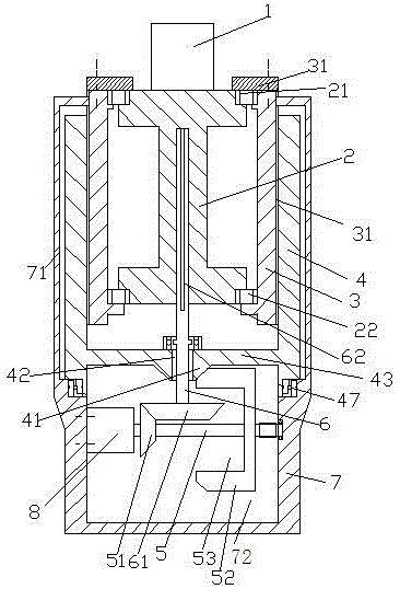
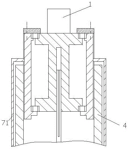
[0013] Attached below Figure 1-2 , the present invention will be described in detail.

[0014] A reduced weight worm machining mechanism for machining a blank 1 into a worm, said worm machining mechanism comprising a blank carrier 2, an externally threaded sleeve 3, an internally threaded drive sleeve 4 and a frame 7. The upper end of the blank carrier 2 is provided with an upper annular flange, and the lower end is provided with a lower annular flange, thereby forming an annular cavity between the upper annular flange and the lower annular flange, forming a The blank carrier 2 of the annular cavity reduces the weight of the worm machining mechanism; the upper end surface of the upper annular flange is used to carry the blank 1, and the upper annular protrusion of the blank carrier 2 The rim and the lower annular flange are axially fixedly installed in the sleeve 3 with external thread relative to the sleeve 3 with external thread through an upper bearing 21 and a lower bear...


PUM


Abstract

A worm machining mechanism lower in weight is used for machining a blank (1) into a worm. The machining mechanism comprises a blank bearing part (2), a sleeve (3) with an external thread, a driving sleeve (4) with an internal thread and a rack (7). An upper ring-shaped flange (211) is arranged at the upper end of the blank bearing part (2), a lower ring-shaped flange (212) is arranged at the lower end of the blank bearing part (2), a ring-shaped cavity (23) is formed between the upper ring-shaped flange (211) and the lower ring-shaped flange (212), and the blank bearing part (2) with the ring-shaped cavity (23) makes the weight of the worm machining mechanism be reduced.

Description

technical field [0001] The application relates to the field of worm machining, in particular to a weight-reduced worm machining mechanism. Background technique [0002] The worm drive is composed of a worm and a worm gear, and the worm is generally the active part. Worms, like threads, can be divided into right-handed and left-handed. Worm drive has the following advantages: 1. Large transmission ratio and compact structure. The number of worm heads is represented by Z1 (generally Z1=1~4), and the number of worm gear teeth is represented by Z2. It can be seen from the transmission ratio formula I=Z2 / Z1 that when Z1=1, that is, the worm is single-headed, and the worm must turn Z2 to turn the worm wheel for one turn, so a large transmission ratio can be obtained. Generally, in power transmission, take The transmission ratio I=10-80; in the indexing mechanism, I can reach 1000. Such a large transmission, such as gear transmission, needs to adopt multi-stage transmission, so...

Claims


Application Information

Patent Timeline
Patent Type & Authority Patents(China)
IPC IPC(8): B23F13/00
Inventor 栾绍根朱金华
Owner JIANGSU HUAXIA HEAVY IND
Why Eureka
Try Eureka