Profile correction machining method for high-precision plane of optical part

A technology of optical parts and processing methods, applied in metal processing equipment, machine tools for surface polishing, manufacturing tools, etc., to achieve the effects of high processing efficiency, low cost, and small removal allowance

Active Publication Date: 2016-03-16
DALIAN UNIV OF TECH
View PDF6 Cites 11 Cited by
  • Summary
  • Abstract
  • Description
  • Claims
  • Application Information

AI Technical Summary

Problems solved by technology

[0007] In view of the above problems, in order to solve the deficiencies of the existing optical parts processing methods, the main purpose of the present invention is to provide a high-precision plane modification processing method for optical parts. Deterministic global shape modification processing, reducing the removal allowance, improving processing efficiency, avoiding surface high-frequency errors and reducing processing costs, and can be applied to the processing of parts of any thickness

Method used


Image

  • Profile correction machining method for high-precision plane of optical part
  • Profile correction machining method for high-precision plane of optical part
  • Profile correction machining method for high-precision plane of optical part

Examples


Embodiment Construction

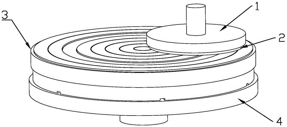
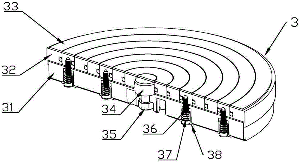
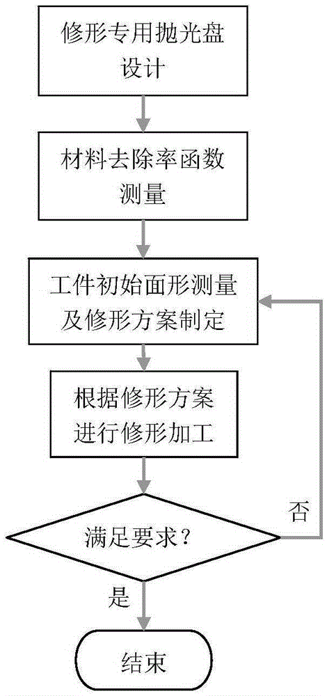
[0030] The invention provides a method for modifying and processing high-precision planes of optical parts. The method of the invention is mainly aimed at processing flat optical parts and can realize deterministic global modification processing of the surface of the optical parts. In this method, on the basis of traditional chemical mechanical polishing or mechanical polishing, the integral polishing disc on the grinding and polishing machine is replaced by a special polishing disc for modification, by removing the polishing pads located in different radial positions on the special polishing disc for modification Process conditions are controlled to obtain different material removal rate functions, and according to the deviation of the initial surface profile of the surface of the workpiece 2 to be processed, the processing time corresponding to the process conditions for various material removal characteristics is designed to realize the modification process of the surface of ...


PUM


Abstract

The invention discloses a profile correction machining method for a high-precision plane of an optical part. According to the method, on the basis of traditional grinding and polishing methods, polishing pads located in annular areas in different radial positions of a special profile correction polishing disc are made not to have a material removing effect through the special profile correction polishing disc, and combined with process condition control, different material removal rate distribution curves are obtained; according to initial surface profile morphology deviation of the surface of a workpiece, machining time of process conditions corresponding to various material removal characteristics is designed, so that profile correction machining of the surface of the workpiece is achieved. An upper disc body of the polishing disc is composed of multiple concentric rings with a lifting function, different surface material removal rate distribution characteristics can be obtained, and deterministic machining is achieved. According to the method, profile correction schemes are designed according to the initial surface profile morphology deviation of the optical part, deterministic material removal machining is carried out on the surface, the total removal allowance is small, machining efficiency is high, and cost is low. The profile correction machining method is suitable for to-be-machined workpieces in different shapes and with different thicknesses.

Description

technical field [0001] The invention belongs to the technical field of optical parts processing, in particular to a method for modifying the shape of a high-precision plane of an optical part. Background technique [0002] Plane optical components are an important part of the optical system, such as the plane reflector in the telescope system, the plane standard mirror in the parabolic mirror inspection system, etc. In these systems, the precision of planar optical components affects the imaging quality and inspection results of the system. In recent years, with the development of optical technology, the number of optical elements in the optical system has continued to show a trend of large numbers and large apertures, such as large astronomical telescopes and high-power laser devices. Taking the National Ignition Facility (NIF) of the United States as an example, it is a huge and complex giant optical project. Its requirements for optical components are unprecedented in te...

Claims


Application Information

Patent Timeline
Patent Type & Authority Applications(China)
IPC IPC(8): B24B29/02B24B1/00
CPCB24B1/00B24B29/02
Inventor 周平邬振刚王林何东山左云盛
Owner DALIAN UNIV OF TECH
Why Eureka
Try Eureka