Sealing ring for rotating shaft

A technology for sealing rings and rotating shafts, which is applied in the direction of engine sealing, engine components, mechanical equipment, etc., can solve the problems of high cost of use, easy leakage, and large creep, and achieve fewer parts, less wear and tear, and lower cost Effect

Inactive Publication Date: 2016-03-16
张理够
View PDF6 Cites 5 Cited by
  • Summary
  • Abstract
  • Description
  • Claims
  • Application Information

AI Technical Summary

Problems solved by technology

[0002] At present, the sealing ring for the rotating shaft is mainly used to seal the sealing body of the rotating shaft. The sealing ring for the rotating shaft in the prior art molds a rubber lip or a polytetrafluoroethylene main lip on the metal skeleton, but due to the rubber lip It is necessary to use a spring ring to exert a radial sealing force on the lip to achieve the sealing effect, and the lip will wear faster. The rotating shaft lip seal ring of the rubber lip has only one main sealing lip. When the lip

Method used


Image

  • Sealing ring for rotating shaft
  • Sealing ring for rotating shaft

Examples


Embodiment 1

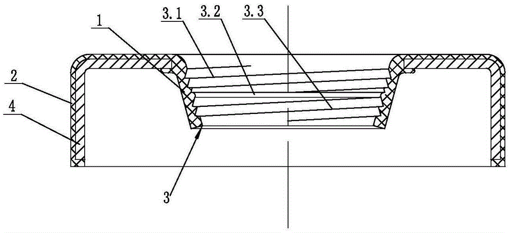
[0015] Such as figure 1 As shown, a sealing ring for a rotating shaft includes a sealing lip 1, an outer diameter sealing body 2 and a sealing rib 3 at the sealing lip 1, the sealing lip 1 is connected with the outer diameter sealing body 2, and the The sealing rib 3 is divided into a first spiral sealing rib 3.1, an annular sealing rib 3.2 and a second spiral sealing rib 3.3, and the annular sealing rib 3.2 is located between the first spiral sealing rib 3.1 and the second spiral sealing rib 3.3, so There is an interference fit between the sealing lip 1 and the rotating shaft. The helical directions of the first spiral sealing rib 3.1 and the second spiral sealing rib 3.3 are the same, so that the outer first spiral sealing rib 3.1 has a pressing effect on the annular sealing rib 3.2, so that the annular sealing rib 3.2 fits better with the rotating shaft close.

[0016] The section of the first spiral sealing rib 3.1 and the second spiral sealing rib 3.3 is triangular (als...

Embodiment 2

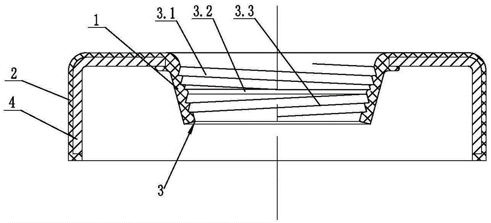
[0020] Such as figure 2 As shown, the helical direction of the first helical sealing rib 3.1 is opposite to that of the second helical sealing rib 3.3.


PUM


Abstract

A sealing ring for a rotating shaft comprises a sealing lip (1), an outer diameter sealing body (2) and sealing ribs (3) at the sealing lip (1), wherein the sealing lip (1) is connected with the outer diameter sealing body (2); the sealing ribs (3) comprise a first spiral sealing rib (3.1), an annular sealing rib (3.2) and a second spiral sealing rib (3.3), and the annular sealing rib (3.2) is located between the first spiral sealing rib (3.1) and the second spiral sealing rib (3.3); the sealing lip (1) is in interference fit with the rotating shaft. Compared with the prior art, the sealing ring has the characteristics that the sealing ring is not abraded easily, the usage cost is low and leakage does not occur easily.

Description

technical field [0001] The invention relates to a sealing ring, in particular to a sealing ring for a rotating shaft. Background technique [0002] At present, the sealing ring for the rotating shaft is mainly used to seal the sealing body of the rotating shaft. The sealing ring for the rotating shaft in the prior art molds a rubber lip or a polytetrafluoroethylene main lip on the metal skeleton, but due to the It is necessary to use a spring ring to exert a radial sealing force on the lip to achieve the sealing effect, and the lip will wear faster. The rotating shaft lip seal ring of the rubber lip has only one main sealing lip. When the lip appears When worn, the sealing ring will easily leak, and timely maintenance is required, which makes the maintenance frequency higher, which in turn makes the use cost and maintenance cost higher; because the PTFE main lip adopts the design of the plane sealing structure, and Due to the high creep property of the polytetrafluoroethyle...

Claims


Application Information

Patent Timeline
IPC IPC(8): F16J15/3232F16J15/3244
CPCF16J15/3232F16J15/3244
Inventor 张理够
Owner 张理够
Why Eureka
Try Eureka