
An electronic fence alarm tester

An electronic fence and tester technology, applied in the field of alarm testers, can solve the problems of poor safety performance and inconvenient detection of electronic fences.

Active Publication Date: 2017-10-31
LISHUI POWER SUPPLY COMPANY OF STATE GRID ZHEJIANG ELECTRIC POWER +2
View PDF6 Cites 0 Cited by
  • Summary
  • Abstract
  • Description
  • Claims
  • Application Information

AI Technical Summary

Problems solved by technology

[0003] The technical problem to be solved by the present invention is to provide an electronic fence alarm tester, which can effectively solve the problems of inconvenience and poor safety performance existing in the detection of existing electronic fences

Method used


Image

  • An electronic fence alarm tester
  • An electronic fence alarm tester
  • An electronic fence alarm tester

Examples


Embodiment Construction

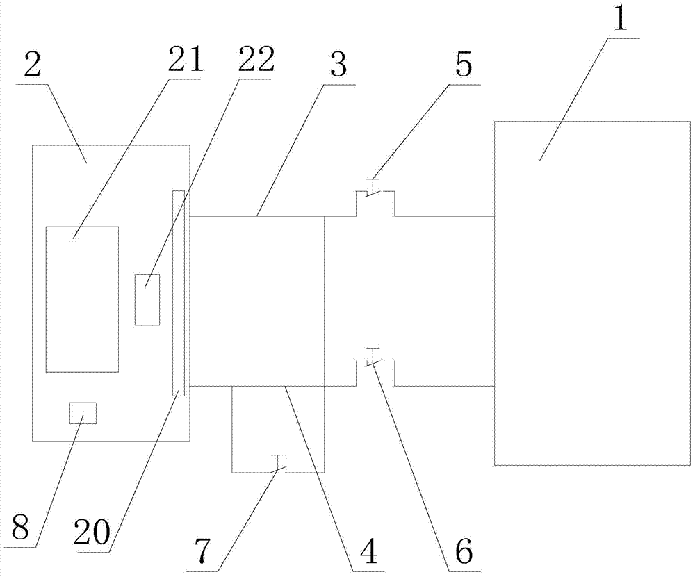
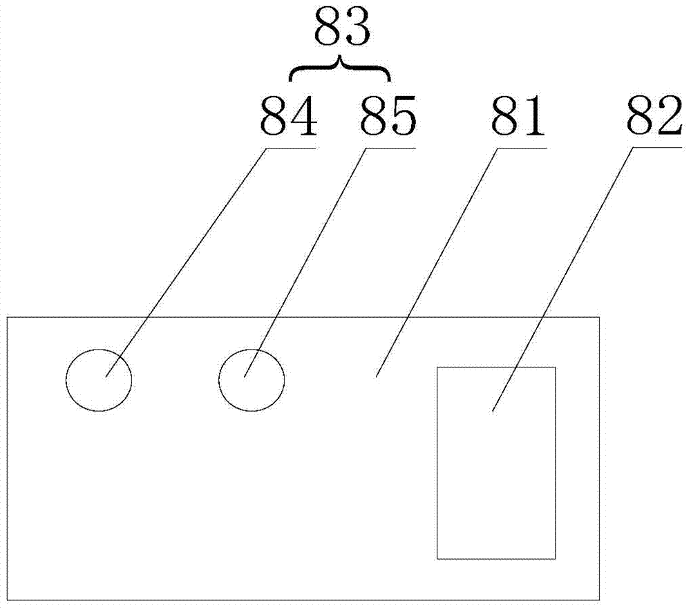
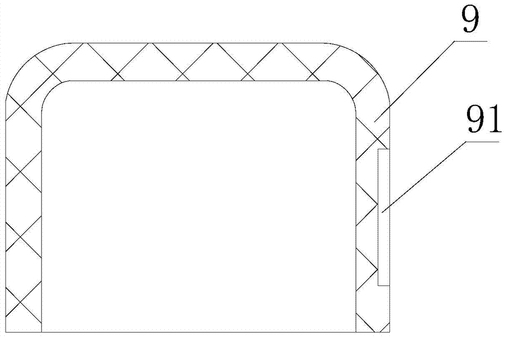
[0017] like figure 1 , figure 2 , image 3 , Figure 4 As shown, an electronic fence alarm tester includes an electronic fence 1 and a mainframe 2, the mainframe 2 is provided with a detection module 21, the mainframe 2 is provided with a receiving port 22, and the electronic fence 1 is connected with a first connected to the mainframe 2. Outgoing line 3 and second outgoing line 4, the first outgoing line 3 is provided with a first detection button 5 that controls the disconnection of the first outgoing line 3, and the second outgoing line 4 is provided with a second outgoing line 4 that controls the disconnection of the second outgoing line 4. Test button 6, the first outgoing line 3 and the second outgoing line 4 are connected with a third test button 7 that controls the short circuit of the first outgoing line 3 and the second outgoing line 4, and the first test button 5 and the second test button 6 are connected in parallel Then it is connected in series with the third...


PUM


Abstract

The invention relates to an electronic fence alarming testing device comprising an electronic fence and a host. A detection module is disposed in the host, which is provided with a receiving port. The electronic fence is connected with a first wire outlet line and a second wire outlet line. The first wire outlet line is provided with a first detection button, and the second wire outlet line is provided with a second detection button. The first wire outlet line and the second wire outlet line are connected with a third detection button. The host is provided with an alarming assembly. The electronic fence alarming testing device is advantageous in that the first wire outlet line and the second wire outlet line can be disconnected under the control of the first detection button and the second detection button, and the short circuit of the first wire outlet line and the second wire outlet line can be realized under the control of the third detection button, and then the receiving port of the host cannot receive the signals, and therefore the alarming assembly of the host can be used to give alarms, and then the operators can use the leads or other replacements to touch the electronic fence for the test; the alarming testing device is safe, convenient, and sensitive.

Description

technical field [0001] The invention relates to an alarm tester, in particular to an electronic fence alarm tester. Background technique [0002] At present, the substations are all in the mode of unattended left-behind personnel. In order to ensure the safe operation of the substation equipment and the security of the substation environment, to prevent people from climbing into the wall without authorization and causing personal electric shock accidents and equipment and equipment anti-theft prevention The electric fence alarm system is installed on the surrounding walls of the substation. After the electric fence alarm system is put into operation, due to the long running time and poor operating environment, faults and defects appear more frequently. Special testing tools, operators usually need to test whether the electronic fence is running normally. They can only use wires or other substitutes to touch the electronic fence to test, which is inconvenient and has unsafe f...

Claims


Application Information

Patent Timeline
Patent Type & Authority Patents(China)
IPC IPC(8): G08B29/12
CPCG08B29/126
Inventor 王勇朱慧华马锁成朱仙洪彭利平陶智赟刘子卓宗海龙
Owner LISHUI POWER SUPPLY COMPANY OF STATE GRID ZHEJIANG ELECTRIC POWER
Learn More