Method for measuring the thickness of boiler water pipes

A measurement method and boiler technology, applied in boiler water pipes, components of steam boilers, steam boilers, etc., can solve the problems of reduced boiler operation efficiency and long construction period of boiler water pipes, and achieve the effect of shortening construction period and stable operation efficiency.

Active Publication Date: 2017-03-22
MITSUBISHI MATERIALS CORP
View PDF8 Cites 0 Cited by
  • Summary
  • Abstract
  • Description
  • Claims
  • Application Information

AI Technical Summary

Problems solved by technology

As a result, the measurement of the thickness of the boiler water pipe requires a long period of time and the operating efficiency of the boiler is reduced.

Method used


Image

  • Method for measuring the thickness of boiler water pipes
  • Method for measuring the thickness of boiler water pipes

Examples


Embodiment Construction

[0025] Next, with reference to the accompanying drawings, specific embodiments of the present invention will be described for understanding of the present invention.

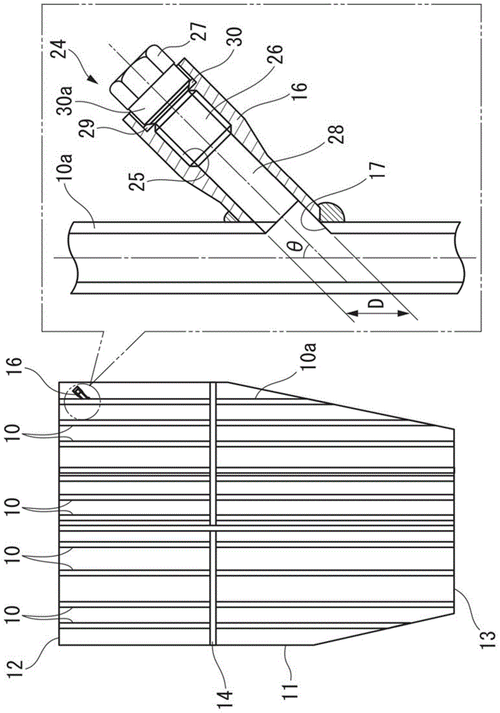
[0026] First, the boiler water pipe 10a in an upright state and other boiler water pipes 10 in an upright state to which the method for measuring the thickness of a boiler water pipe according to an embodiment of the present invention is applied (refer to figure 1 )Be explained.

[0027] A plurality of boiler water tubes 10, 10a are vertically arranged at predetermined intervals in the boiler water tube panel 11, and water passes through the inside thereof. The upper ends of the respective boiler water pipes 10, 10a are suspended from beams of the building, whereby the arrangement of the respective boiler water pipes 10, 10a in the boiler water pipe panel 11 is fixed.

[0028] Moreover, the intermediate part in the longitudinal direction of each boiler water tube 10,10a communicates with the header 14. As shown...


PUM


Abstract

An inspection hole (17) is formed on the side of the boiler water pipe (10a) in the longitudinal direction, and the base side of the conduit (16) is connected to the inspection hole (17). Usually, a closing member (24) is installed on the conduit (16), and the measurement When the thickness of the boiler water pipe (10a) is determined, remove the sealing member (24) from the conduit (16), insert the ultrasonic probe (18) into the boiler water pipe (10a) from the front side of the conduit (16), and make the ultrasonic probe (18) Move inside the boiler water pipe (10a).

Description

technical field [0001] The present invention relates to a method of measuring the thickness of boiler water pipes by using an interpolation type ultrasonic thickness measurement, which is performed, for example, as a part of investigating the aging of boiler water pipes. [0002] This application claims priority based on Patent Application No. 2013-138994 for which it applied in Japan on July 2, 2013, and uses the content here. Background technique [0003] Conventionally, as part of the investigation of deterioration of small-diameter boiler water pipes, for example, the ultrasonic flaw detection apparatus described in Patent Document 1 has been used to perform in-line ultrasonic thickness measurement of boiler water pipes. Here, the interpolation type ultrasonic thickness measurement of the boiler water pipe is performed in the following procedure. First, a part of the boiler water pipe is cut to form an inspection hole, and an ultrasonic flaw detection probe is inserted ...

Claims


Application Information

Patent Timeline
Patent Type & Authority Patents(China)
IPC IPC(8): F22B37/02G01B17/02G01N29/04
CPCF22B37/002F22B37/02F22B37/18G01B17/02F22B37/10G01N29/04G01N29/043G01N2291/044
Inventor 小隈信博广濑慎平庄司和也中村雅敏安田泰夫
Owner MITSUBISHI MATERIALS CORP
Why Eureka
Try Eureka