
Magnetic feeding oil removing machine

A degreasing machine and magnetic technology, applied in the centrifuge and other directions, can solve the problems of incomplete dumping, unreasonable design of the centrifugal unloading method, affecting the service time of the degreasing machine, etc., and achieve the effect of fast unloading speed

Inactive Publication Date: 2016-03-23
高嘉智能设备(嘉兴)股份有限公司
View PDF1 Cites 0 Cited by
  • Summary
  • Abstract
  • Description
  • Claims
  • Application Information

AI Technical Summary

Problems solved by technology

[0002] At present, the deoiling method of parts processed by cold heading machines, CNC machine tools and other processing machines is usually to manually add the parts to the centrifuge for deoiling. The centrifuge adopts the principle of mechanical centrifugation. Through the high-speed rotation of the centrifugal cylinder, The oil is thrown out and then collected, but the equipment used in this deoiling method has low working efficiency, and when adding parts, it is easy to cause danger to the operator
[0003] China Invention Patent Application No. 201310277797.5 discloses an automatic degreasing machine. Although the machine improves the production efficiency and solves the safety problem when the operator adds parts, the design of the centrifugal discharge method of the device is unreasonable
The centrifugation and unloading of this device are carried out in two units. First, the parts must be sent into the centrifuge bucket, and then after each centrifuge degreasing is completed, the motor is paused, and then the centrifuge bucket is poured out with the cylinder. Parts, this way of centrifuging and then dumping the parts not only wastes time, but also greatly reduces the working efficiency of the degreaser, and if the dumping angle of the centrifugal bucket is not enough, it is easy to dump incompletely
In addition, the constantly changing position of the centrifugal bucket is not only easy to damage, but also easily causes the balance deviation of the centrifugal bucket, resulting in unbalanced separation and collection, which ultimately affects the service life of the degreasing machine
In addition, the feeding of this oil removal machine is directly fed by chain plates, which is prone to problems of oil leakage and follow-up

Method used


Image

  • Magnetic feeding oil removing machine
  • Magnetic feeding oil removing machine
  • Magnetic feeding oil removing machine

Examples


Embodiment Construction

[0016] The present invention will be further described below in conjunction with drawings and embodiments.

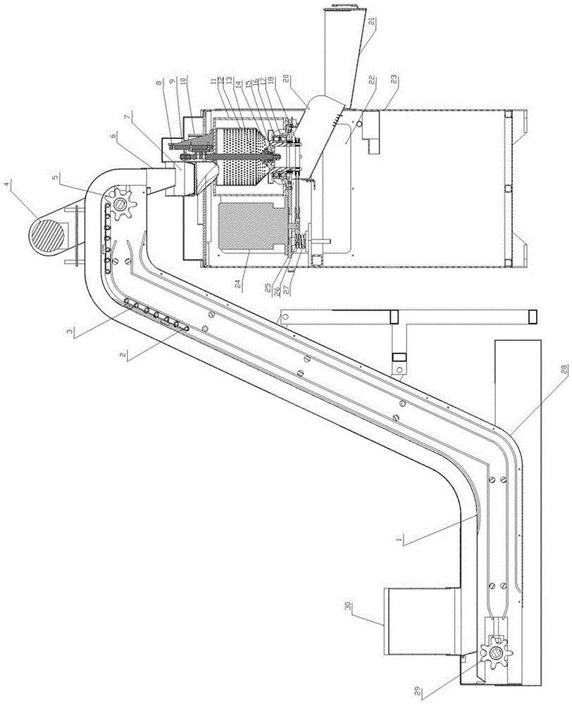
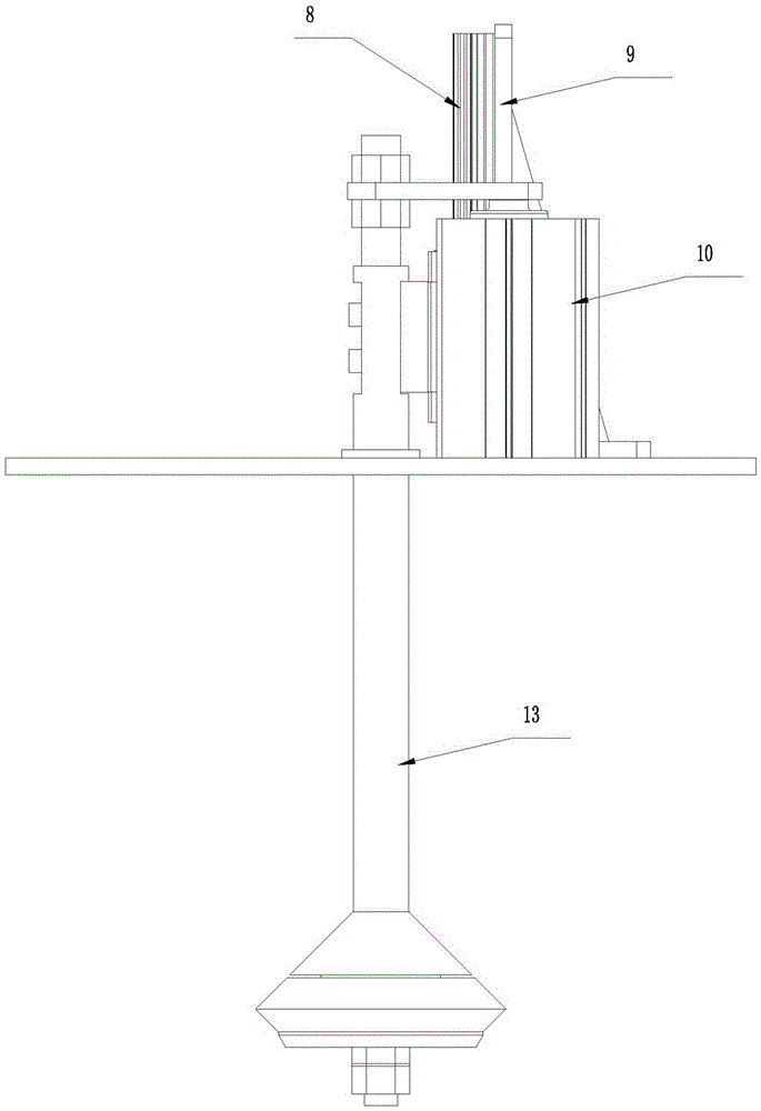
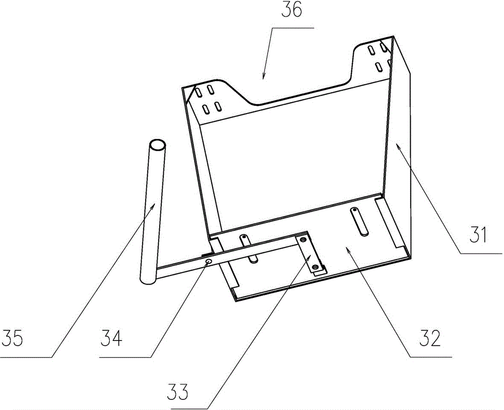
[0017] As shown in the figure, the present invention includes a frame, a conveying device and a centrifugal device arranged on the frame. The transmission device is connected with the centrifugal device. The transmission device includes a transmission chain plate 2, a driving sprocket 5, a driven sprocket 29, and a reduction motor 4. The two ends of the transmission chain plate 2 are sleeved on the driving sprocket 5 and the driven sprocket 5. On the moving sprocket 29, the driving sprocket 5 is connected with the reduction motor 4, the transmission device also includes a stainless steel transmission groove 1, the transmission chain plate 2 is provided with magnets 3 at intervals, and the transmission chain The plate 2 is arranged close to the bottom of the stainless steel transmission tank 1, the feeding end of the stainless steel transmission tank 1 is bent downward, ...


PUM


Abstract

The invention relates to a magnetic feeding oil removing machine. The magnetic feeding oil removing machine comprises a machine frame, a conveying device and a centrifugal device, wherein the conveying device and the centrifugal device are arranged on the machine frame and are connected. The conveying device comprises a conveying chain plate, a driving chain wheel, a driven chain wheel and a speed reduction motor, wherein the two ends of the conveying chain plate are arranged on the driving chain wheel and the driven chain wheel respectively in a surrounding mode, and the driving chain wheel is connected to the speed reduction motor; the conveying device further comprises a stainless steel conveying groove; the conveying chain plate is provided with magnets at intervals and is arranged adjacent to the lower side of the bottom of the stainless steel conveying groove, the discharge end of the stainless steel conveying groove is bent downwards, a discharge hopper is arranged at the port of the discharge end, and the driving chain wheel is arranged on the inner side of the discharge end. Oil slinging holes are formed in the wall of an inner centrifugal barrel, an oil outlet is formed in the bottom of an outer centrifugal barrel, and an oil accumulation box is arranged at the part, below the oil outlet, of the machine frame.

Description

technical field [0001] The invention relates to a magnetic feeding and degreasing machine for deoiling parts processed by processing machine tools such as cold heading machines, numerical control machine tools, and automatic tapping machines. Background technique [0002] At present, the deoiling method of parts processed by cold heading machines, CNC machine tools and other processing machines is usually to manually add the parts to the centrifuge for deoiling. The centrifuge adopts the principle of mechanical centrifugation. Through the high-speed rotation of the centrifugal cylinder, The oil is thrown out and then collected, but the equipment used in this deoiling method has low working efficiency, and when adding parts, it is easy to cause danger to the operator. [0003] Chinese invention patent application number 201310277797.5 discloses an automatic degreasing machine. Although the machine improves production efficiency and solves the safety problem when operators add...

Claims


Application Information

Patent Timeline
Patent Type & Authority Applications(China)
IPC IPC(8): B04B5/00B04B7/00B04B7/08B04B11/04
CPCB04B5/00B04B7/00B04B7/08B04B11/04
Inventor 孙水根郭传国
Owner 高嘉智能设备(嘉兴)股份有限公司
Learn More