
An optical fiber stripping device based on the new generation of information technology

An information technology, a new generation of technology, applied in the field of optical fiber stripping devices, can solve the problems of short optical fibers, insufficient cutting, low work efficiency, etc., to avoid the problem of fiber core damage, reduce manual intervention, and achieve a high degree of automation Effect

Active Publication Date: 2021-12-03
聊城八月瓜大数据服务有限公司
View PDF6 Cites 0 Cited by
  • Summary
  • Abstract
  • Description
  • Claims
  • Application Information

AI Technical Summary

Problems solved by technology

Usually, the skin of the optical fiber is cut and removed by manual operation with the help of a knife. However, during the operation, because the cutting force cannot be controlled manually, the stripping depth cannot be accurately controlled, and it is easy to crush the fiber core or shorten the fiber. , affecting the normal use of optical fiber, and time-consuming and labor-intensive, the work efficiency is low
However, when the existing stripping device is in use, since the cross-section of the optical fiber is usually circular, when the cutting surface is fixed, it is easy to have insufficient cutting, so that the outer skin of the optical fiber is partially adhered, which is not conducive to the separation of the outer skin.
At the same time, the optical fiber is squeezed by the cutting tool, and the cutting position is prone to deviation and distortion, which is not conducive to the normal peeling operation
[0003] Aiming at the deficiencies of the prior art, the present invention provides an optical fiber stripping device based on a new generation of information technology, which has the advantages of multi-directional fixation, ring cutting and better stripping quality, and solves the problem of poor stripping quality of general stripping equipment The problem

Method used


Image

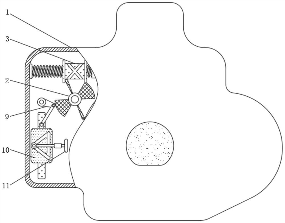
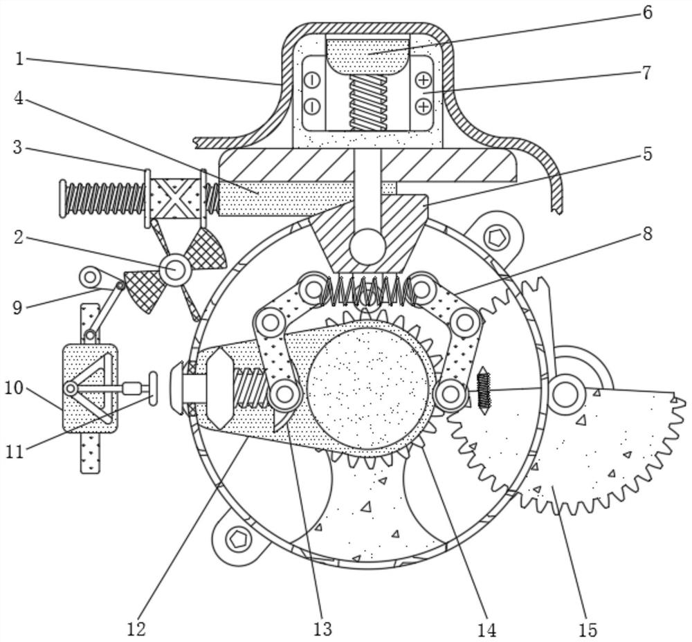
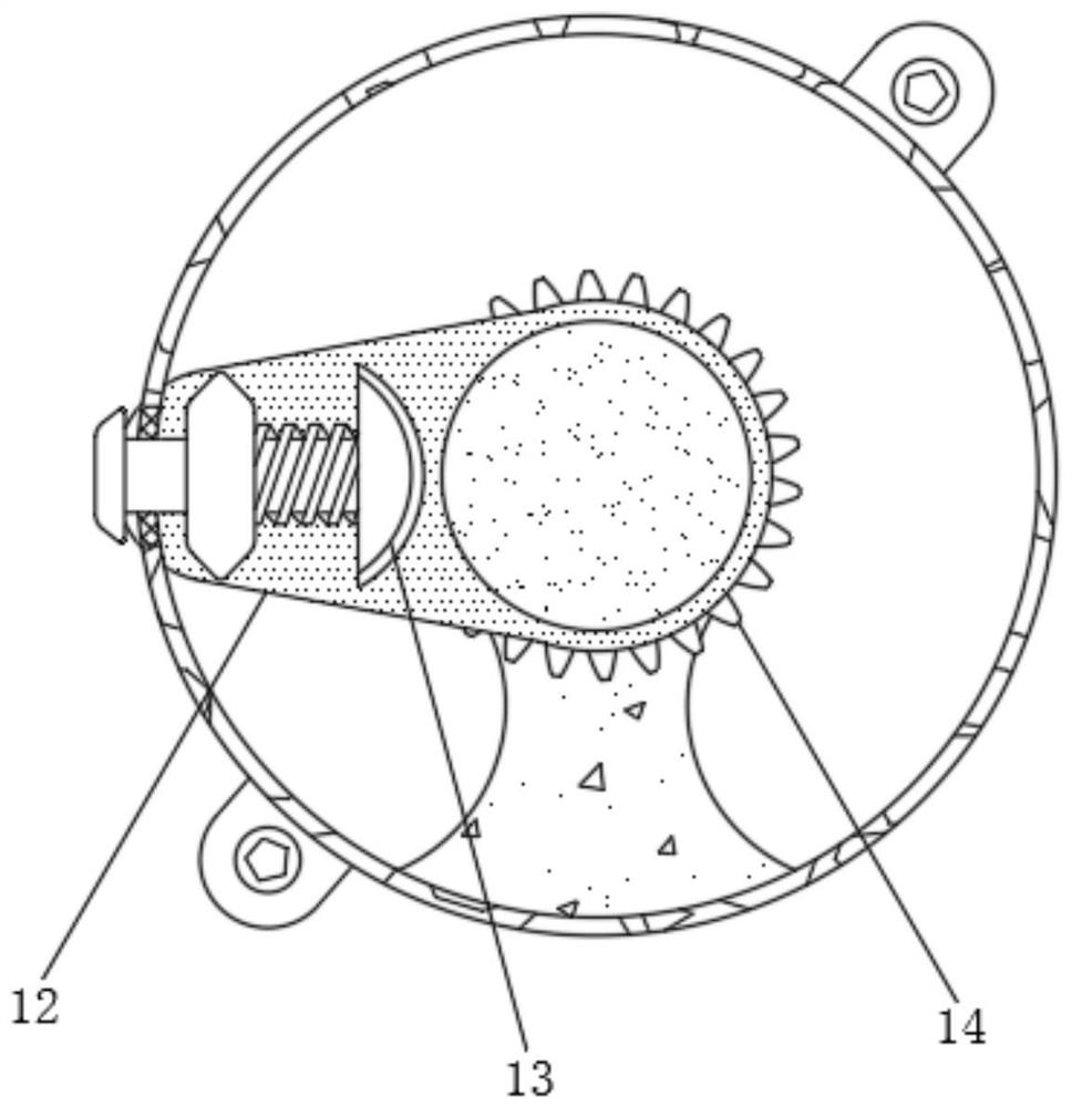
  • An optical fiber stripping device based on the new generation of information technology
  • An optical fiber stripping device based on the new generation of information technology
  • An optical fiber stripping device based on the new generation of information technology

Examples


Embodiment Construction

[0023] The following will clearly and completely describe the technical solutions in the embodiments of the present invention with reference to the accompanying drawings in the embodiments of the present invention. Obviously, the described embodiments are only some, not all, embodiments of the present invention. Based on the embodiments of the present invention, all other embodiments obtained by persons of ordinary skill in the art without making creative efforts belong to the protection scope of the present invention.

[0024] see Figure 1-4 , an optical fiber stripping device based on a new generation of information technology, including a housing 1, the surface of the housing 1 is provided with a through hole, the size of which shall not be smaller than the size of the through hole of the second rotating plate 12 and the hole of the ring gear 14, the housing 1 through The size of the hole is adapted to the size of the optical fiber. The inside of the housing 1 is movably c...


PUM


Abstract

The invention relates to the technical field of optical fiber equipment, and discloses an optical fiber stripping device based on a new generation of information technology. Limiting effect, the position of the optical fiber remains constant, avoiding the twisting of the optical fiber due to the extrusion of the cutter, so that the peeling operation can be carried out smoothly, and the subsequent peeling operation is triggered by the principle of capacitance, increasing the linkage between structures , which makes the operation more convenient and has a high degree of automation. Adjust the position of the cutter so that the cutter can automatically cut into the outer skin of the optical fiber and control the cutting thickness by itself. 1. Control the fiber core damage problem, effectively improve the stripping quality, automatically rotate and cut the outer skin of the optical fiber, and completely cut the outer skin of the optical fiber, free hands, reduce manual intervention, and have higher work efficiency.

Description

technical field [0001] The invention relates to the technical field of optical fiber equipment, in particular to an optical fiber stripping device based on a new generation of information technology. Background technique [0002] Optical fiber is a carrier for light transmission, which is widely used in medicine, sensors, artistic underground detection and other fields. During the construction process of optical fibers, in order to connect them with each other, the outer layer needs to be stripped off. Usually, the skin of the optical fiber is cut and removed by manual operation with the help of a knife. However, during the operation, because the cutting force cannot be controlled manually, the stripping depth cannot be accurately controlled, and it is easy to crush the fiber core or shorten the fiber. , affect the normal use of optical fiber, and waste time and effort, and work efficiency is low. However, when the existing stripping device is in use, since the cross secti...

Claims


Application Information

Patent Timeline
Patent Type & Authority Patents(China)
IPC IPC(8): G02B6/245
CPCG02B6/245
Inventor 孙民鑫
Owner 聊城八月瓜大数据服务有限公司
Learn More