
A thread processing method with large modulus and large lead

A technology of thread processing and large lead, applied in the field of thread processing, can solve the problems of difficult thread processing, long working length, long processing cycle, etc., and achieve the effect of improving processing efficiency, reducing vibration and improving quality

Active Publication Date: 2019-03-05
贵州振华群英电器有限公司(国营第八九一厂)
View PDF4 Cites 0 Cited by
  • Summary
  • Abstract
  • Description
  • Claims
  • Application Information

AI Technical Summary

Problems solved by technology

[0002] Thread processing is to cut the workpiece on a lathe, especially for the processing of trapezoidal thread and modulus thread. Since the traditional processing method is to process the thread initially, it is processed according to the method of bilateral cutting. During the cutting process, the cutting tool is subjected to greater resistance, which makes it more difficult to process threads; and for threads with large lead and large modulus, according to this processing method, due to the working length of processing It is longer, so that vibration occurs during the cutting process, resulting in chipping of the knife; if the grooving knife is used for grooving and forming, and then the forming knife is used for modification processing, which will result in a longer processing cycle and lower efficiency

Method used


Image

  • A thread processing method with large modulus and large lead

Examples


Embodiment 1

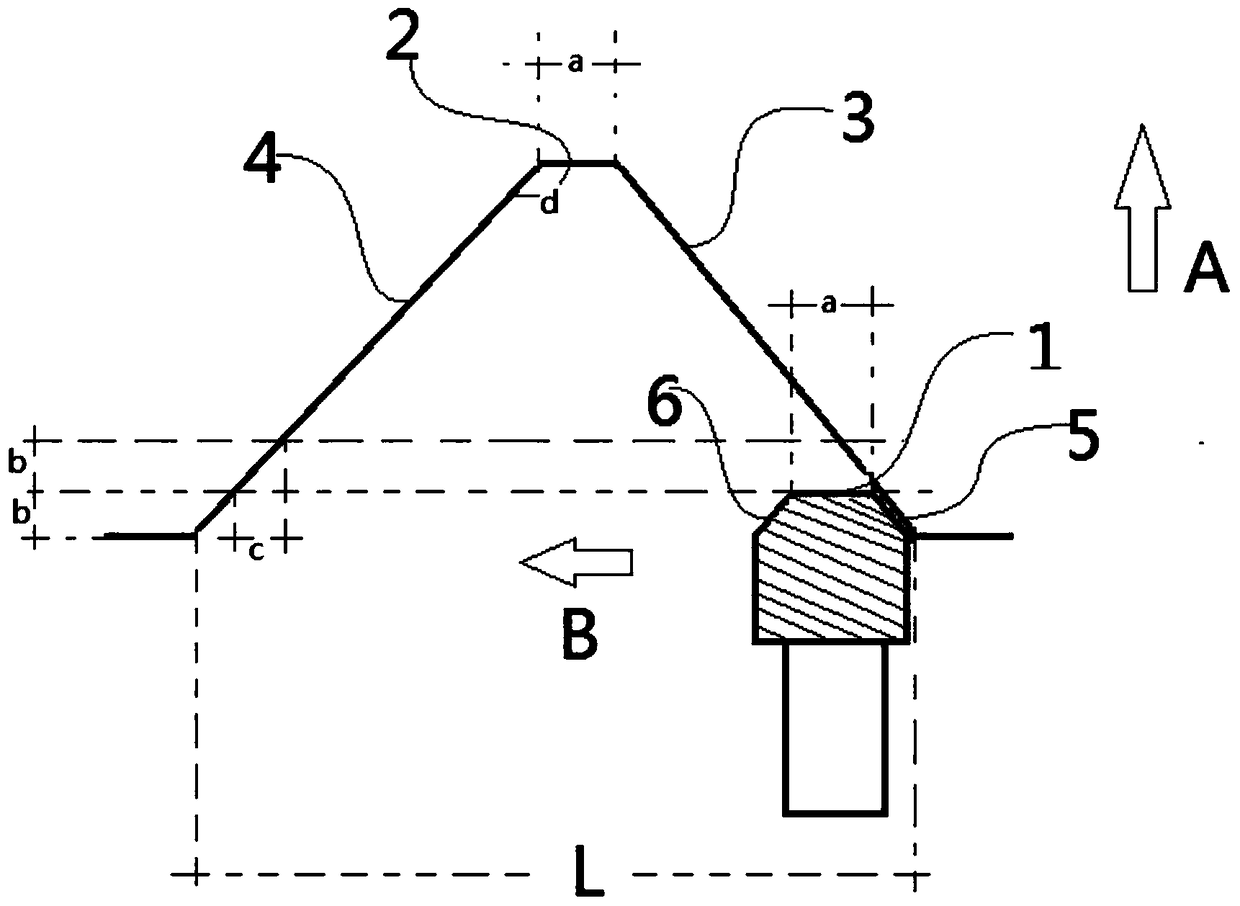
[0030] A thread processing method with large modulus and large lead, cutting the threading tool radially toward the workpiece to form an initial thread groove with a depth b; after the threading tool exits, the initial thread groove with a depth b Move the threading tool in the B direction until the thread opening distance reaches L, and complete the first layer of processing; then move the threading tool in the A direction to the second layer of thread grooves with a cutting depth of b, and move the threading in the A direction Before the knife starts cutting the second layer, move the top of the threading tool to the right side wall of the thread for a horizontal distance c, and then cut. After the threading tool exits, move the threading tool in the direction of B until the distance reaches Complete the processing of the second layer; according to the above method in turn, move the threading tool in the B direction until the distance reaches a, and during the processing of ...

Embodiment 2

[0035]On the basis of Embodiment 1, the others are the same as in Embodiment 1, the threading cutter is moved in the B direction, and the contact point of the threading cutter is softened before moving. The softening treatment is to use neutral oxygen-pyridine to heat to 700-800° C., and rapidly cool to room temperature with water.

Embodiment 3

[0037] On the basis of Embodiment 1, the others are the same as in Embodiment 1. The threading cutter is moved in the direction A, and the contact point 1 of the threading cutter is softened to a depth of 0.1-0.5 before moving. mm. The softening treatment is carried out by heating to 700-800°C with neutral oxygen-flame acetylene, and rapidly cooling to room temperature with water.


PUM


Abstract

The invention relates to the technical field of thread machining, in particular to a large-modulus and large-lead thread machining method. The structure of a thread cutter is studied, the structure of a thread groove is studied, then the structure of the thread groove and the structure of the thread cutter are combined, thread cutting machining process steps are adjusted, the feed size, the cutting mode and the size in the machining process are controlled, and therefore vibration of the cutter in the cutting process is reduced, the phenomenon of tipping and cutter beating is avoided, and machining efficiency is improved.

Description

technical field [0001] The invention relates to the technical field of thread processing, in particular to a thread processing method with large modulus and large lead. Background technique [0002] Thread processing is to cut the workpiece on a lathe, especially for the processing of trapezoidal thread and modulus thread. Since the traditional processing method is to process the thread initially, it is processed according to the method of bilateral cutting. During the cutting process, the cutting tool is subjected to greater resistance, which makes it more difficult to process threads; and for threads with large lead and large modulus, according to this processing method, due to the working length of processing It is longer, so that vibration occurs during the cutting process, resulting in the phenomenon of chipping and hitting the knife; if the grooving knife is used for grooving and forming, and then the forming knife is used for modification processing, it will result in...

Claims


Application Information

Patent Timeline
Patent Type & Authority Patents(China)
IPC IPC(8): B23G1/02
CPCB23G1/02
Inventor 王建明
Owner 贵州振华群英电器有限公司(国营第八九一厂)
Learn More