
a wire feeding device

A wire feeding device and wire feeding wheel technology, used in arc welding equipment, manufacturing tools, welding equipment, etc., can solve the problems of uneven wire feeding, large size, easy vibration, etc., and achieve stable wire feeding, small size, and weight. lightening effect

Active Publication Date: 2017-11-28
SHANGHAI HUGONG ELECTRIC WELDING MACHINE MFG
View PDF6 Cites 0 Cited by
  • Summary
  • Abstract
  • Description
  • Claims
  • Application Information

AI Technical Summary

Problems solved by technology

[0002] The existing wire feeding mechanism has large volume, high cost, low speed wire feeding, unstable wire feeding, easy vibration, easy to produce uncertain wire blocking phenomenon, and is not suitable for small household economical products.

Method used


Image

  • a wire feeding device
  • a wire feeding device
  • a wire feeding device

Examples


Embodiment Construction

[0032] The advantages of the present invention will be further elaborated below in conjunction with the accompanying drawings and specific embodiments.

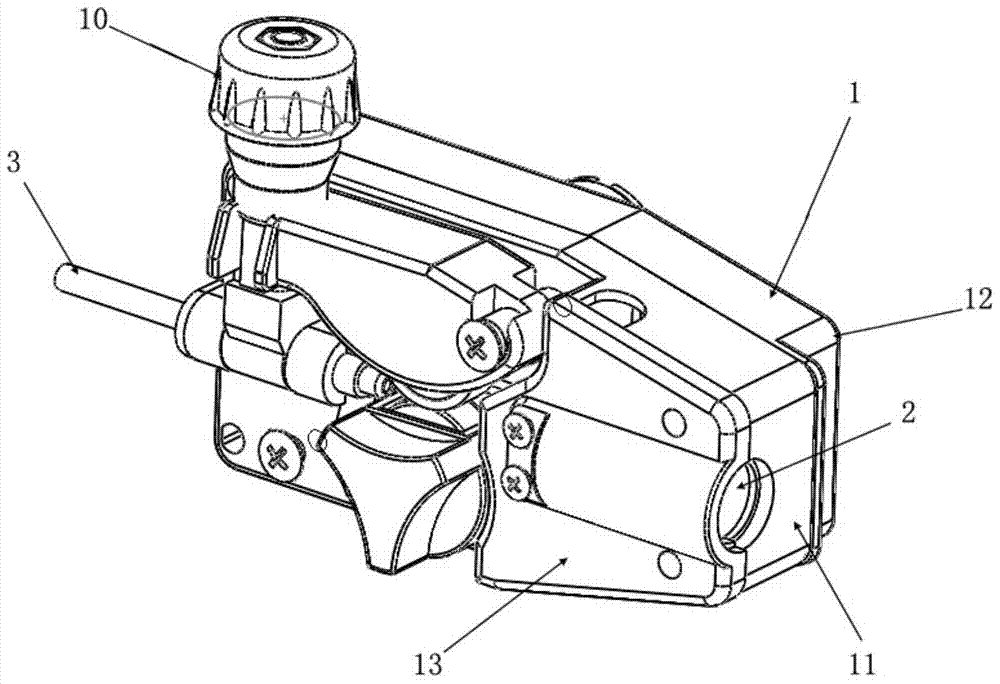
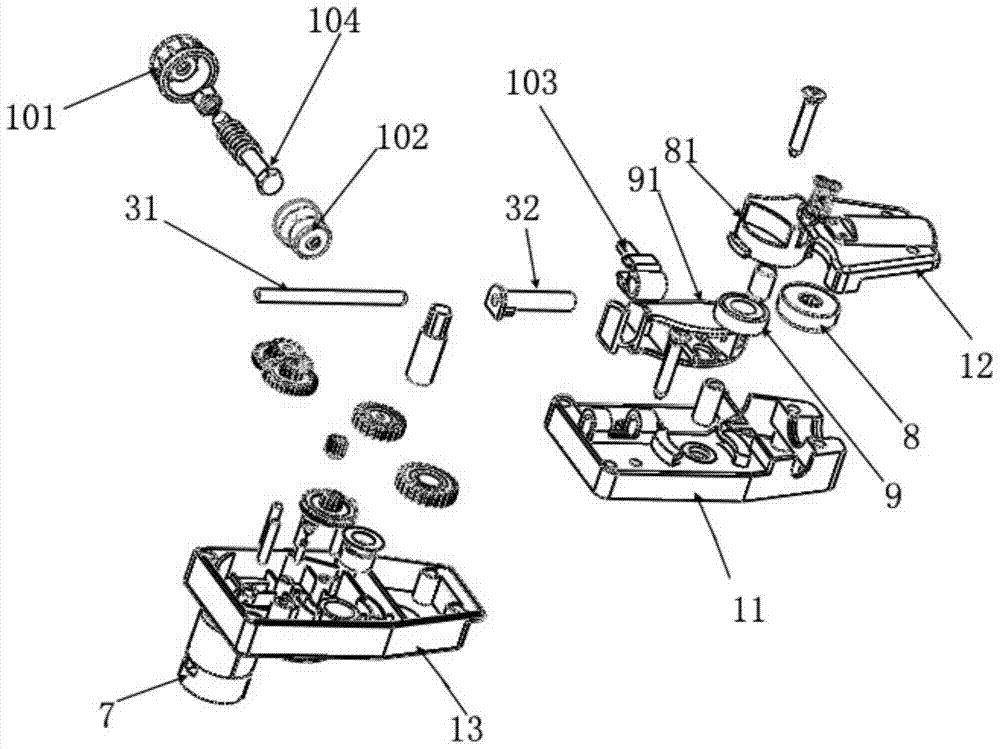
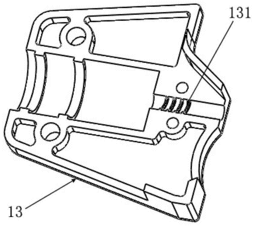
[0033] Such as figure 1 , figure 2 , Figure 4 and Figure 5 As shown, the present invention discloses a wire feeding device, the wire feeding device includes a housing 1, a welding torch interface 2 is provided at the front end of the housing 1, and a welding torch interface 2 is provided at the rear end of the housing 1. Wire feeding interface 3; in the housing 1, a drive input wheel 4, a transmission wheel 5, and a drive output wheel 6 are arranged in sequence, and the drive input wheel 4 is connected to the drive device 7, and the drive output wheel 6 is connected to the wire feeding wheel 8; the wire feeding device also has a wire pressing wheel 9 opposite to the wire feeding wheel 8, and an adjusting device 10 for adjusting the pressing degree of the wire feeding.

[0034] Preferably, as figure 1 , figure 2 as w...


PUM


Abstract

The invention provides a wire feeding device which comprises a shell. A welding gun joint is arranged at the front end of the shell. A wire feeding joint is arranged at the rear end of the shell. A drive input wheel, a transmission wheel and a drive output wheel which are sequentially meshed are arranged in the shell. The drive input wheel is connected with a drive device and the drive output wheel is connected with a wire feeding wheel. The wire feeding device is further provided with a wire pressing wheel arranged opposite to the wire feeding wheel and an adjusting device for adjusting the pressing degree of a fed wire. The wire feeding device has the beneficial effects of being small in size, high in economical efficiency, stable in wire feeding, practical in function, high in manufacturing efficiency and capable of being conveniently assembled in batches.

Description

technical field [0001] The invention relates to a wire feeding device, in particular to a low-power automatic wire feeding device. Background technique [0002] The existing wire feeding mechanism has large volume, high cost, low-speed wire feeding, unstable wire feeding, easy vibration, easy to produce uncertain wire blocking phenomenon, and is not suitable for small household economical products. Contents of the invention [0003] In order to overcome the above-mentioned technical defects, the object of the present invention is to provide a low-power automatic wire feeding device. [0004] The invention discloses a wire feeding device. The wire feeding device includes a casing, a welding torch interface is arranged at the front end of the casing, and a wire feeding interface is arranged at the rear end of the casing; A drive input wheel, a transmission wheel and a drive output wheel meshed with each other in turn are provided, the drive input wheel is connected to the d...

Claims


Application Information

Patent Timeline
Patent Type & Authority Patents(China)
IPC IPC(8): B23K9/133
CPCB23K9/133
Inventor 不公告发明人
Owner SHANGHAI HUGONG ELECTRIC WELDING MACHINE MFG
Learn More