Limitable welding gun traveling mechanism for welding machine

A traveling mechanism and welding torch technology, applied in welding equipment, auxiliary welding equipment, welding/cutting auxiliary equipment, etc., can solve the problems of impossible manual operation and increase of extra cost.

Inactive Publication Date: 2016-03-23
韦红生
View PDF6 Cites 4 Cited by
  • Summary
  • Abstract
  • Description
  • Claims
  • Application Information

AI Technical Summary

Problems solved by technology

This makes manual operation impossible due to the locking function of the thread
And setting up another mechanism to replace this power drive system will increase additional costs

Method used


Image

  • Limitable welding gun traveling mechanism for welding machine
  • Limitable welding gun traveling mechanism for welding machine
  • Limitable welding gun traveling mechanism for welding machine

Examples


Embodiment Construction

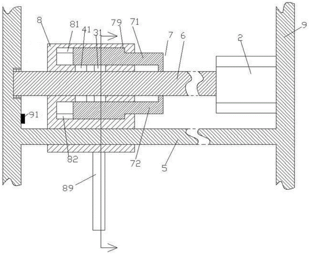
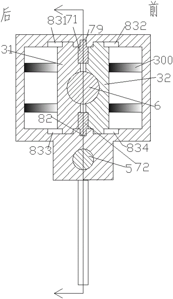
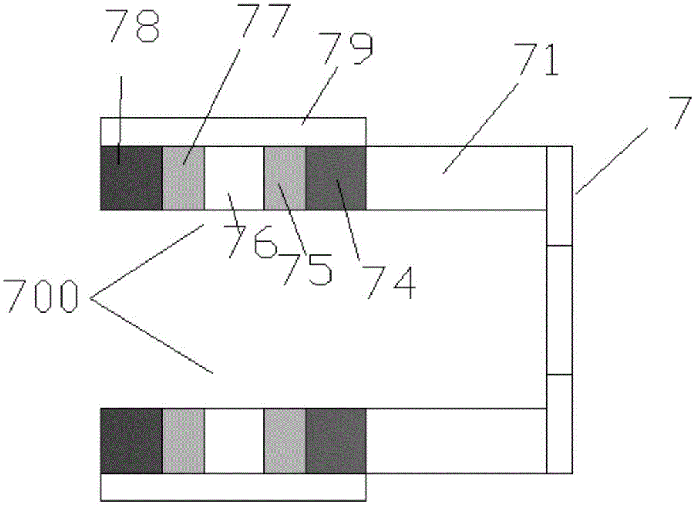
[0011] Combine below Figure 1-4 The present invention will be described in detail.

[0012] A position-limitable welding torch traveling mechanism for a welding machine according to an embodiment, used for operating the welding torch to move during the welding process, including a support frame 9, a traveling support housing 8 and fixed on the lower side of the traveling support housing 8 A welding torch connecting portion 89 for connecting with a welding torch, wherein the left and right extending screw rod 6 driven by the motor 2 and rotatably installed on the support frame 9 passes through the upper part of the traveling support housing 8, and is connected with the The extended sliding guide rod 5 of the effect of the fixed connection of the support frame 9 passes through the bottom of the walking frame housing 8, and the threaded clamping block pair and the sliding clamping block pair are respectively arranged in the walking frame housing 8, and the threaded clamping bloc...


PUM


Abstract

The invention discloses a limitable welding gun traveling mechanism for a welding machine and used for operating a welding gun to move in the welding process. The mechanism comprises a support frame (9), a traveling stand shell (8) and a welding gun connection portion (89) which is fixed to the lower side of the traveling stand shell (8) and used for being connected with the welding gun, wherein a threaded rod (6) which is driven by a motor (2) and rotatably installed on the support frame (9) and extends in the left-right direction penetrates through the upper portion of the traveling stand shell (8), a sliding guide rod (5) which is fixedly connected with the support frame (9) and extends in the left-right direction penetrates through the lower portion of the traveling stand shell (8), the traveling stand shell (8) is internally provided with a threaded clamping block pair and a siding clamping block pair, and the threaded clamping block pair comprises a front threaded block (32) and a rear threaded block (31) and can make a threaded concave portion be clamped and fitted to a threaded rod (6) under the action of a jacking and pressing elastic component (300).

Description

technical field [0001] The invention relates to the field of welding, in particular to a welding torch traveling mechanism which can be used for a welding machine and can be limited. Background technique [0002] In the field of welding, due to the improvement of automation requirements, it is often necessary to automatically control the walking and speed of the welding torch. In the existing technology, a thread driving method is often used to drive and realize the walking motion of the welding torch. Such a driving method has advantages, such as precise transmission and position locking function after power off. [0003] However, there are also disadvantages in these powered approaches. For example, in some specific welding situations, it is necessary to manually operate the travel distance range and travel speed of the welding torch. This makes manual operation impossible due to the locking function of the threads. And additionally setting up mechanism to replace this...

Claims


Application Information

Patent Timeline
Patent Type & Authority Applications(China)
IPC IPC(8): B23K37/02
CPCB23K37/0247B23K37/0205
Inventor 韦红生
Owner 韦红生
Why Eureka
Try Eureka