Clamping force and clamping speed online controllable robot gripper

A robot gripper, gripping speed technology, applied in the direction of program control manipulators, manipulators, manufacturing tools, etc., can solve the problem that the gripping speed cannot be programmed online, does not have force perception, and cannot detect the gripping workpiece, etc. Stable and flexible effect

Inactive Publication Date: 2016-03-23
SHANGHAI JIAO TONG UNIV
View PDF8 Cites 8 Cited by
  • Summary
  • Abstract
  • Description
  • Claims
  • Application Information

AI Technical Summary

Problems solved by technology

Most of the robotic grippers that are widely used in factories as robots are facing the following shortcomings: (1) can only control the opening and closing; (2) the clamping force is adjustable offline but cannot be programmed online in real time, such as pneumatic grippers The clamping force of the gripper can be adjusted by manually adjusting the opening and closing of the valve offline, but it cannot be controlled in real time through computer programming; (3) The clamping speed cannot be programmed online; (4) Without adding a force sensor, Does not have force perception, cannot detect whether the workpiece is successfully clamped
This technology utilizes the rigid transmission of gears to convert the rotational motion of the motor into the opening and closing motion of the fingers. The grasping force is segmented control, which can only realize the segmental controllability of the grasping force, and cannot realize the continuous controllability of the grasping force. Adjustment, and in order to achieve grasping force feedback, the gripper must additionally install sensor seats and force tactile sensors at the end of the finger, making the overall structure more complex and redundant

Method used


Image

  • Clamping force and clamping speed online controllable robot gripper
  • Clamping force and clamping speed online controllable robot gripper
  • Clamping force and clamping speed online controllable robot gripper

Examples


Embodiment 1

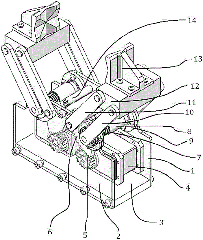
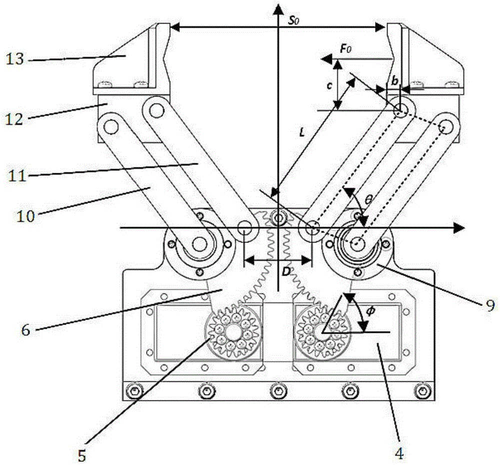
[0025] Such as figure 1 As shown, this embodiment includes: a support structure, fingers 13, steering gear 4 connected in sequence, a gear transmission mechanism, a gear shaft 8, a pair of active connecting rods 10, a horizontal plate 12, a pair of passive connecting rods 11 and a rotating shaft 14 , wherein: the horizontal plate 12 is set horizontally, the finger 13 is vertically set above the horizontal plate 12; the steering gear 4 is symmetrically set in the supporting structure, and the two ends of the gear shaft 8 are respectively connected with a pair of driving connecting rods 10; the rotating shaft 14 is parallel to the gear The shaft 8 is set, and the two ends of the rotating shaft 14 are respectively connected with a pair of passive connecting rods 11; one end of the active connecting rod 10 is connected with the horizontal plate 12, and the other end is connected with the gear shaft 8; one end of the passive connecting rod 11 is connected with the horizontal plate ...


PUM


Abstract

A clamping force and clamping speed online controllable robot gripper comprises steering engines, fingers, a bottom plate, a main substrate, an auxiliary substrate, driven connecting rods, a rotating shaft, a gear, sector-shaped gears, a gear shaft, driving connecting rods and a transverse plate. The gears are meshed with the sector-shaped gears, the sector-shaped gears are connected with the gear shaft, and a torsion spring is arranged between the sector-shaped gears and the gear shaft; driving connecting rods are located on the outer side of the main substrate and the outer side of the auxiliary substrate respectively, one ends of the driving connecting rods are connected with the two ends of the gear shaft respectively, and the other ends of the driving connecting rods are connected through the transverse plate; one ends of the driven connecting rods are connected with the two ends of the transverse plate respectively, and the other ends of the driven connecting rods are connected through the rotating shaft; and the steering engines are arranged in a bilateral symmetry manner and are fixedly arranged on the inner side of the main substrate. The steering engines output the rotating angle and the rotating angular speed to the fingers, the clamping force and the clamping speed of the gripper can be controlled in an online manner, and the robot gripper is simple in structure, reasonable in design and stable and flexible in work.

Description

technical field [0001] The invention relates to a technology in the field of robot manufacturing, in particular to a robot gripper with online controllable clamping force and clamping speed. Background technique [0002] With the advent of the era of Industry 4.0, a particularly important trend will be individualized mass production. In order to realize personalized production, the factory must have the ability to deal with the processing of various parts, so the reprogrammability of processing equipment is essential. Most of the robotic grippers that are widely used in factories as robots are facing the following shortcomings: (1) can only control the opening and closing; (2) the clamping force is adjustable offline but cannot be programmed online in real time, such as pneumatic grippers The clamping force of the gripper can be adjusted by manually adjusting the opening and closing of the valve offline, but it cannot be controlled in real time through computer programming;...

Claims


Application Information

Patent Timeline
Patent Type & Authority Applications(China)
IPC IPC(8): B25J9/10
CPCB25J9/1035B25J9/109
Inventor 曹其新达兴鹏梁爽
Owner SHANGHAI JIAO TONG UNIV
Why Eureka
Try Eureka