Pneumatic finger with replaceable contact

A technology of pneumatic fingers and contacts, applied in manipulators, chucks, manufacturing tools, etc., can solve the problems of difficulty in completing complex and fine movements, the influence of pneumatic fingers on the accuracy of movements, and the difficulty in adjusting the contact force of the grasping point. Take the effect of flexibility, better anti-skid effect and ingenious structure

Inactive Publication Date: 2018-06-22
CHANGZHOU COLLEGE OF INFORMATION TECH
View PDF0 Cites 3 Cited by
  • Summary
  • Abstract
  • Description
  • Claims
  • Application Information

AI Technical Summary

Problems solved by technology

The disadvantages of this structure are: 1) The bending action that can be achieved only by controlling the gas pressure of the single cavity is very limited, and the types of objects that can be grasped are limited; 2) The pose and contact force of the pneumatic finger are very limited. It is difficult to carry out independent control, which affects its movement accuracy, and it is difficult to complete complex and fine movements; 3) The inner side of the bending direction of the pneumatic finger is just a limiting strain layer, which makes the clamping part less flexible; 4) When dealing with different grasping objects, when grasping When the posture is basically the same, it is difficult to adjust the contact force of the grasping point, or it is difficult to increase or decrease the size of the contact surface according to the different grasping objects, so the adaptability is limited; 5) Pneumatic finger positive pressure inflatable clamping Usually the action speed is faster when the air is released, and the action speed is slower when the air is released, and its efficiency needs to be improved.

Method used


Image

  • Pneumatic finger with replaceable contact
  • Pneumatic finger with replaceable contact
  • Pneumatic finger with replaceable contact

Examples


Embodiment 1

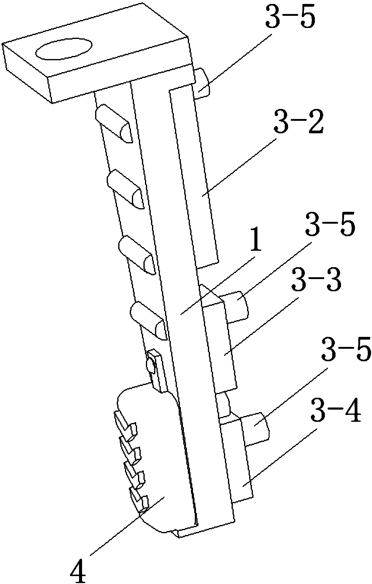
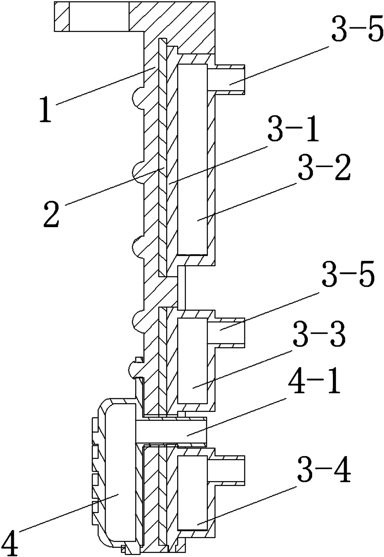
[0030] See Figure 1 to Figure 5 , the pneumatic finger with replaceable contacts in this embodiment includes a base frame 1 , a supporting shrapnel 2 , an outer drive assembly 3 and a detachable contact 4 .

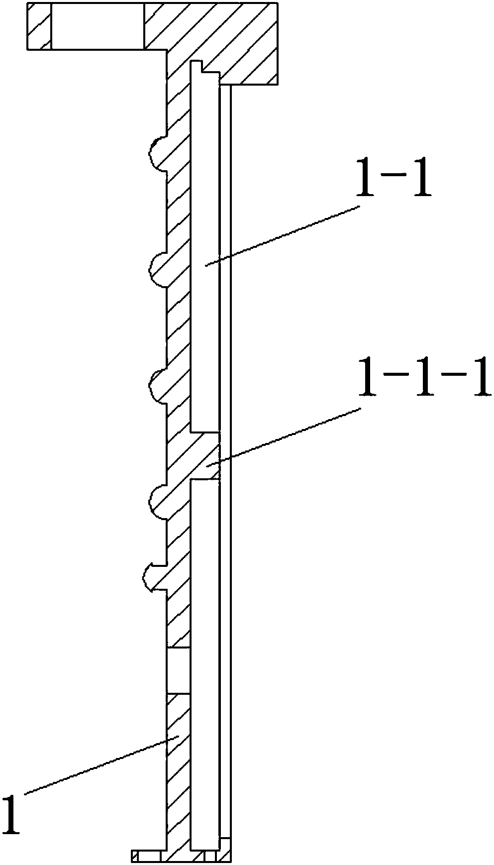
[0031] The bottom of the base frame 1 is mounted on the end of the robot. The width of the base frame 1 gradually decreases from top to bottom. The supporting elastic piece 2 is arranged in the base skeleton 1 . The outer drive assembly 3 includes a base sheet 3-1 and a bottom-finger drive cavity 3-2, a middle-finger drive cavity 3-3 and a fingertip drive cavity 3- 5. The substrate sheet 3-1 is detachably fixed on one side of the substrate skeleton 1 . The driving cavity 3-2 for the base of the finger, the driving cavity 3-3 for the middle finger and the driving cavity 3-5 for the fingertip are all provided with air pipes 3-5 communicating with the respective inner cavities. The finger root drive cavity 3-2, the middle finger drive cavity 3-3 and the fingertip drive...

Embodiment 2

[0037] This embodiment is basically the same as Embodiment 1, except that the detachable contact 4 is a solid structure with elasticity.


PUM


Abstract

The invention discloses a pneumatic finger with a replaceable contact. The pneumatic finger comprises a base framework, a supporting elastic sheet, an outer side driving assembly and the detachable contact, the supporting elastic sheet is arranged in the base framework, the outer side driving assembly comprises a base sheet and further comprises a finger root driving cavity, a finger middle driving cavity and a finger tip driving cavity which are sequentially arranged from top to bottom, the base sheet is detachably fixed to one side of the base framework, and the finger root driving cavity, the finger middle driving cavity and the finger tip driving cavity are each provided with an air pipe communicating to respective cavities; and the finger root driving cavity, the finger middle drivingcavity and the finger tip driving cavity generate deformation after inflation of gas to drive upper, middle and lower parts of the base framework to bend to the other side. The pneumatic finger is ingenious in structure, the outer side driving assembly adopts three-section type independent ventilation drive, the base framework grabbing motion range is increased, motion is more flexible, local motion of a finger tip and a finger middle can be achieved, the motion efficiency is improved, and energy consumption is reduced.

Description

technical field [0001] The invention relates to a pneumatic finger with replaceable contacts. Background technique [0002] With the gradual subdivision of the global industrial field, the quality requirements for industrial products are gradually increasing, the product replacement cycle is shortened, and the product variety is increasing. The demand for flexible production lines and soft robots is gradually increasing. At the same time, with the improvement of people's consumption level and the acceleration of population aging, agriculture, fishery, food industry, emergency rescue and disaster relief, medical industry and other fields have varying degrees of demand for soft robots. Soft robots can be applied to the grasping of fragile items, dynamic sorting of various workpieces, grasping and picking of agricultural products, grasping and fishing of seafood of different shapes, sorting of soft foods, grasping of dangerous goods, medical supplies sorting etc. In order to ...

Claims


Application Information

Patent Timeline
Patent Type & Authority Applications(China)
IPC IPC(8): B25J15/00
CPCB25J15/0009
Inventor 涂琴颜鹏眭翔岳东海吴琪王鹏苏沛群刘光新
Owner CHANGZHOU COLLEGE OF INFORMATION TECH
Why Eureka
Try Eureka