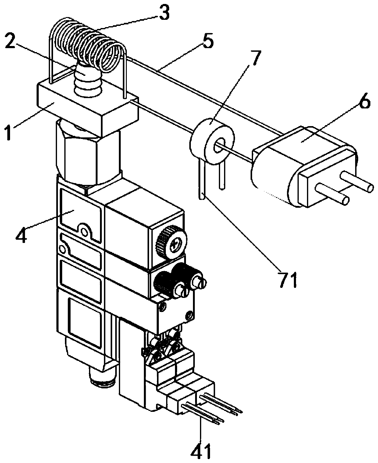
Full-automatic combustible gas on-line monitoring tail gas ignition device

A fully automatic, gas technology, applied in the direction of combustion ignition, measuring devices, combustion methods, etc., can solve the problems of high environmental requirements, prone to danger, unsuitable sensitivity, etc.

Inactive Publication Date: 2020-06-05
合肥科晶材料技术有限公司
View PDF7 Cites 0 Cited by
  • Summary
  • Abstract
  • Description
  • Claims
  • Application Information

AI Technical Summary

Problems solved by technology

[0002] At present, when the atmosphere sintering equipment uses flammable gas for sintering, the tail gas needs to be ignited to prevent the leakage of flammable gas. The common way is to use pulse high-voltage ignition, use instantaneous high-voltage spark ignition, and use UV ultraviolet rays in the combustion process. Monitor the flame or thermocouple to detect the temperature of the flame at the gas outlet. Due to the need for automatic safety processing, flame detection is required to determine whether the exhaust gas is leaking, so that when the flame is extinguished, the ignition is re-ignited, or the alarm is used to cut off the intake air. The detection method, UV detection is to detect the ultraviolet rays of the flame. This method has too high requirements on the environment. The influence of external light sources, too small flame and the pollution of the sensor lens will cause false alarms, which will cause false alarms for the intervention of subsequent automatic safety measures. Action, and the flame temperature detection of the thermocouple, due to the characteristics of the thermocouple temperature sensor, when the flame starts to burn or the flame temperature is extinguished, the heat conduction characteristics of the thermocouple cause it to sense the temperature change. It takes 10-30 seconds. For leakage The sensitivity of the measurement is not applicable and prone to dangerous probability, so inventing a new type of exhaust gas ignition device can solve the above problems

Method used


Image

  • Full-automatic combustible gas on-line monitoring tail gas ignition device

Examples


Embodiment Construction

[0021] The following will clearly and completely describe the technical solutions in the embodiments of the present invention with reference to the accompanying drawings in the embodiments of the present invention. Obviously, the described embodiments are only some, not all, embodiments of the present invention. Based on the embodiments of the present invention, all other embodiments obtained by persons of ordinary skill in the art without creative efforts fall within the protection scope of the present invention.

[0022] In describing the present invention, it is to be understood that the terms "opening", "upper", "lower", "thickness", "top", "middle", "length", "inner", "surrounding" etc. Indicating orientation or positional relationship is only for the convenience of describing the present invention and simplifying the description, and does not indicate or imply that the components or elements referred to must have a specific orientation, be constructed and operated in a sp...


PUM


Abstract

The invention discloses a full-automatic combustible gas on-line monitoring tail gas ignition device, which comprises a ceramic base and an electric heating wire heater mounted on the upper part of the ceramic base. A jet nozzle is mounted in the center of the ceramic base, an outlet in the top end of the jet nozzle is close to the electric heating wire heater, and the bottom end of the jet nozzleis fixedly connected with a gas flow sensor through a thread. The necessary conditions of combustible gas combustion are utilized, the state of the necessary conditions is controllable on line, safecombustion of combustible gas is realized, the combustion state is monitored, and thus full-automatic combustible gas on-line tail gas ignition is achieved.

Description

technical field [0001] The invention belongs to the field of combustible gas monitoring, in particular to a fully automatic combustible gas on-line monitoring tail gas ignition device. Background technique [0002] At present, when the atmosphere sintering equipment uses flammable gas for sintering, the tail gas needs to be ignited to prevent the leakage of flammable gas. The common way is to use pulse high-voltage ignition, use instantaneous high-voltage spark ignition, and use UV ultraviolet rays in the combustion process. Monitor the flame or thermocouple to detect the temperature of the flame at the gas outlet. Due to the need for automatic safety processing, flame detection is required to determine whether the exhaust gas is leaking, so that when the flame is extinguished, the ignition is re-ignited, or the alarm is used to cut off the intake air. The detection method, UV detection is to detect the ultraviolet rays of the flame. This method has too high requirements on ...

Claims


Application Information

Patent Timeline
Patent Type & Authority Applications(China)
IPC IPC(8): F23Q7/10F23Q7/24G01D21/02
CPCF23Q7/10F23Q7/24G01D21/02
Inventor 邾根祥朱沫浥江晓平王伟
Owner 合肥科晶材料技术有限公司
Why Eureka
Try Eureka