
Indenting machine

A creasing machine and pressure wheel technology, which can be applied to other household appliances, household appliances, applications, etc., can solve the problems of unsuitable pipe creasing, inconvenient portability, and high cost of use, and achieve long service life, reasonable design, and easy operation Effect

Active Publication Date: 2016-03-23
ZHEJIANG DEQING CONCEPTFE PLASTIC PROD
View PDF3 Cites 0 Cited by
  • Summary
  • Abstract
  • Description
  • Claims
  • Application Information

AI Technical Summary

Problems solved by technology

Some current creasing machines are not suitable for creasing pipes, and they are not convenient to carry, and the cost of use is relatively high

Method used


Image

  • Indenting machine
  • Indenting machine
  • Indenting machine

Examples


Embodiment 1

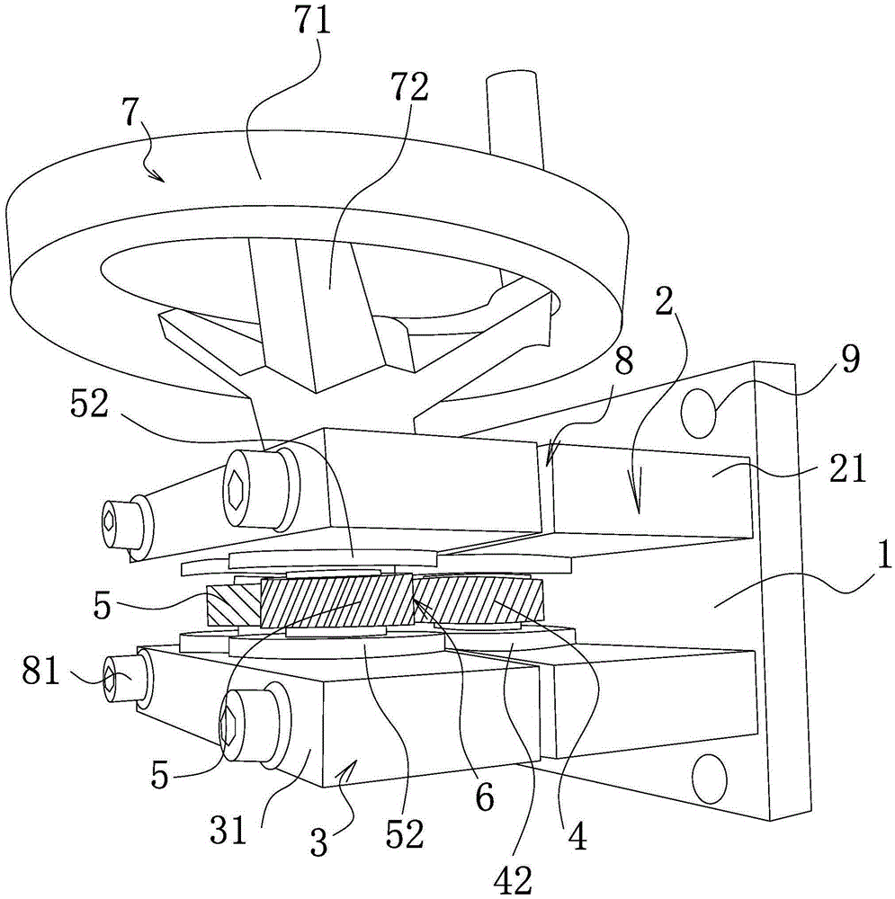
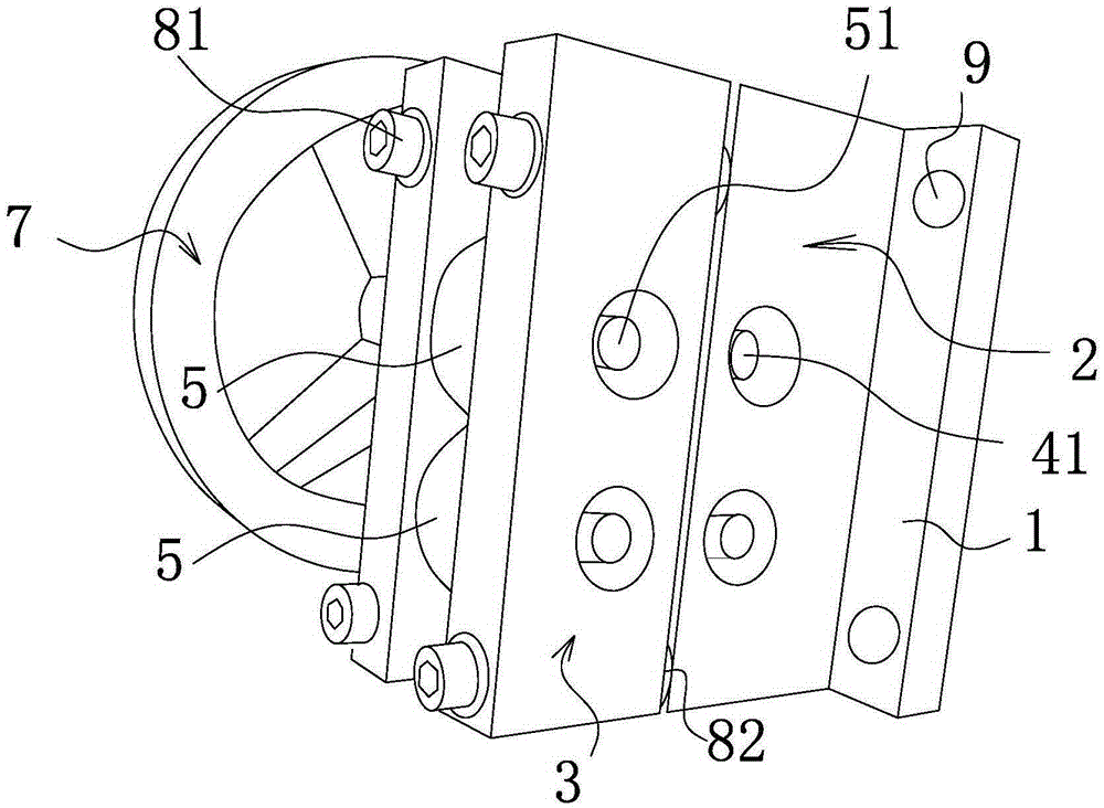
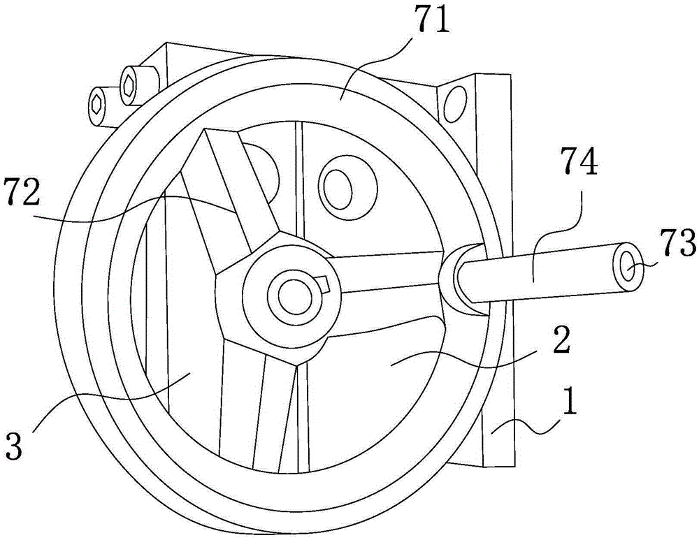
[0023] Such as Figure 1-5 As shown, the creasing machine includes a base 1, a lower frame body 2 is arranged on the base 1, an upper frame body 3 is arranged above the lower frame body 2, at least one lower pressing wheel 4 is arranged on the lower frame body 2, and the upper frame body 3 There is at least one upper pressing roller 5 capable of cooperating with the lower pressing roller 4, an embossing channel 6 is formed between the lower pressing roller 4 and the upper pressing roller 5, and any one of the upper pressing roller 5 or the lower pressing roller 4 is connected with The driving device 7 capable of driving its rotation is connected, and a height adjustment mechanism 8 capable of adjusting the size of the embossing passage 6 is provided between the upper frame body 3 and the lower frame body 2 .

[0024] The upper frame body 3 includes two opposing upper side plates 31, the upper pressure roller 5 is mounted on the upper rotating shaft 51, and the two ends of the ...

Embodiment 2

[0028] Such as Figure 6-7 As shown, in this embodiment, a detachable fixing part 11 is provided at the bottom of the base 1. The fixing part 11 includes strip-shaped rubber pads 111 arranged on both sides of the bottom of the base 1. The bottom of the strip-shaped rubber pad 111 has an arc-shaped part 112 , the outer surface of the arc portion 112 is provided with a number of uniformly distributed rubber protrusions 113, and each strip-shaped rubber pad 111 is also pierced with a number of horizontally distributed and vertically arranged metal support columns 114, the upper end of the metal support column 114 and the base 1 fixed connection, a number of trapezoidal metal protrusions 114a are provided at the lower end of the metal support column 114, the vertical length of the metal support column 114 is smaller than the vertical thickness of the strip-shaped rubber pad 111, and there is also a bottom of the strip-shaped rubber pad 111 The bottom metal clamping block 115, the ...


PUM


Abstract

The invention belongs to the technical field of machining devices and particularly relates to an indenting machine. The indenting machine comprises a base. A lower frame is arranged on the base. An upper frame is arranged above the lower frame. At least one downward-pressing wheel is arranged on the lower frame. At least one upward-pressing wheel capable of being matched with the downward-pressing wheels is arranged on the upper frame. An embossing channel is formed between the downward-pressing wheels and the upward-pressing wheels. Any one of the upward-pressing wheels or the downward-pressing wheels is connected with a drive device capable of driving the corresponding wheel to rotate. A height adjusting mechanism capable of adjusting the size of the embossing channel is arranged between the upper frame and the lower frame. Compared with the prior art, the indenting machine has the beneficial effects that design is reasonable, a pipeline can be indented conveniently, and the indenting machine is convenient to carry and install; the structure is firm, the service life is long, and cost is saved; installation is reliable and convenient, and the machine can be conveniently located after being moved; the machine is convenient and easy to use and can be conveniently operated by a worker; and the indenting machine is of an anti-seismic and anti-skidding structure and is prevented from being moved.

Description

technical field [0001] The invention belongs to the technical field of processing devices, and in particular relates to an indentation machine. Background technique [0002] At present, creasing machines include automatic creasing machines and manual creasing machines. Automatic creasing machines have a high degree of automation and high efficiency, but the cost is very expensive. Compared with the automatic indentation machine, the manual indentation machine has a simpler structure and lower cost. The manual indentation machine usually operates the handle connected to the rotating shaft to turn the rotating shaft, and the rotating shaft drives the indentation knife to press down through the transmission device. Some creasing machines are not suitable for creasing pipes, and they are not convenient to carry, and the cost of use is relatively high. Contents of the invention [0003] The object of the present invention is to solve the above problems and provide a creasing m...

Claims


Application Information

Patent Timeline
Patent Type & Authority Applications(China)
IPC IPC(8): B29C59/04B29L23/00
CPCB29C59/043B29L2023/22
Inventor 邱剑锷
Owner ZHEJIANG DEQING CONCEPTFE PLASTIC PROD
Learn More