A frame beam installation method in which trailing edge strips are not separated in aircraft structure

A technology of aircraft structure and installation method, applied in aircraft parts, fuselage frame, fuselage and other directions, can solve the problems of affecting structural load transmission, non-axial connection holes, etc., to improve connection strength, avoid assembly stress, installation method Convenient and fast effects

Active Publication Date: 2018-06-05
SHENYANG AIRCRAFT DESIGN INST AVIATION IND CORP OF CHINA
View PDF6 Cites 0 Cited by
  • Summary
  • Abstract
  • Description
  • Claims
  • Application Information

AI Technical Summary

Problems solved by technology

When the outer skin is disassembled, the connection between the frame and the beam will be separated in this part of the original configuration, and the connection holes will be out of alignment. When reassembling, there will be assembly stress at the bolt connection, which will affect the load transmission of the structure.

Method used


Image

  • A frame beam installation method in which trailing edge strips are not separated in aircraft structure
  • A frame beam installation method in which trailing edge strips are not separated in aircraft structure

Examples


Embodiment Construction

[0018] In order to make the objectives, technical solutions and advantages of the present invention clearer, the technical solutions in the embodiments of the present invention will be described in more detail below in conjunction with the drawings in the embodiments of the present invention. In the drawings, the same or similar reference numerals denote the same or similar elements or elements having the same or similar functions throughout. The described embodiments are some, but not all, embodiments of the invention. The embodiments described below by referring to the figures are exemplary and are intended to explain the present invention and should not be construed as limiting the present invention. Based on the embodiments of the present invention, all other embodiments obtained by persons of ordinary skill in the art without creative efforts fall within the protection scope of the present invention. Embodiments of the present invention will be described in detail below ...


PUM


Abstract

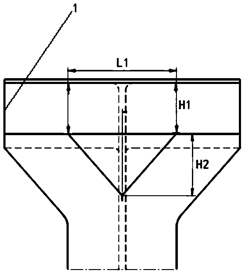
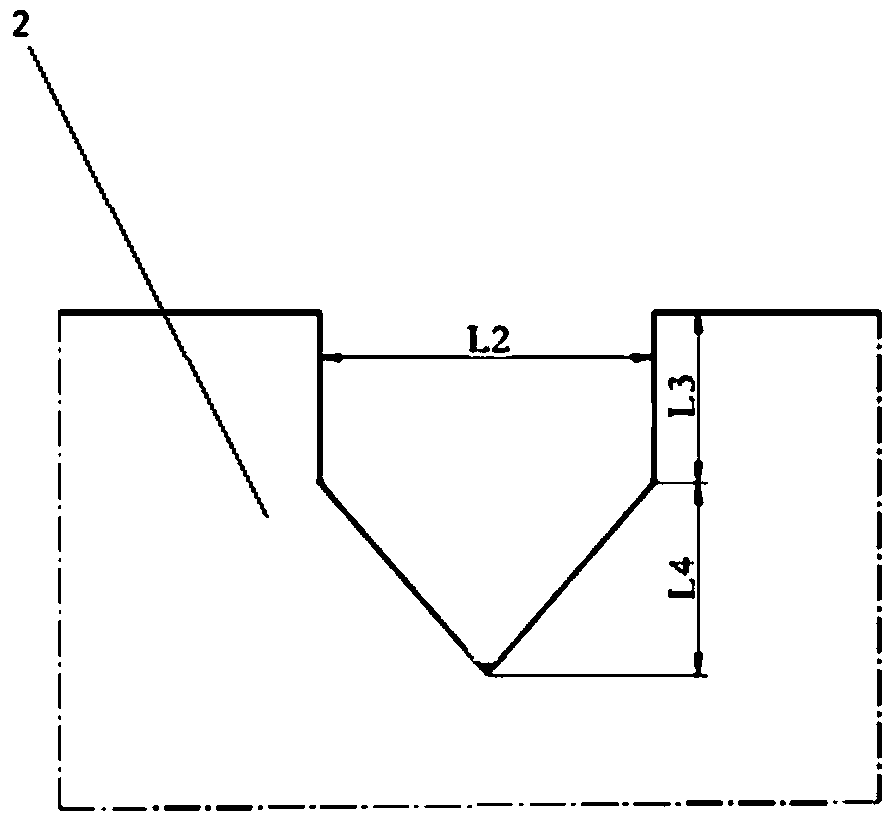
The invention discloses a frame and beam installation method capable of preventing connection separation of a trailing edge strip in a plane structure. The frame and beam installation method includes the following steps that firstly, the number of frame and beam connecting bolt assemblies is determined according to the load in the connecting position of a frame and a beam, and the frame and beam connecting bolt assemblies include the first bolt assemblies and the second bolt assemblies; secondly, the width size of the non-detachable areas in the connection position of the frame and the beam is determined; thirdly, the reserved compensation size for lap joint of the beam and a skin is determined; fourthly, the area of the opening size of the skin is determined; fifthly, the non-detachable areas of the frame and the beam are fixedly connected through the first bolt assemblies; and sixthly, the other areas except for the non-detachable areas of the skin, frame and beam are detachably connected through the second bolt assemblies. By means of the method, assembling stress is avoided, connecting strength is improved, and the connecting design quality of the structure is effectively improved.

Description

technical field [0001] The invention relates to the technical field of aviation manufacturing, in particular to a method for installing frame girders in which trailing edge strips are connected without separation in an aircraft structure. Background technique [0002] There are many frame-beam butt joint structures in the aircraft structure, and the outer skin connected to some parts is detachable. When the outer skin is disassembled, the connection between the frame and the beam will be separated in this part of the original configuration, and the connection holes will be out of axis. When reassembling, there will be assembly stress at the bolt connection, which will affect the load transmission of the structure. [0003] Therefore, a technical solution is desired to overcome or at least alleviate at least one of the above-mentioned problems of the prior art. Contents of the invention [0004] The object of the present invention is to provide a frame girder installation ...

Claims


Application Information

Patent Timeline
Patent Type & Authority Patents(China)
IPC IPC(8): B64C1/06
CPCB64C1/061
Inventor 王美琦王德刚胡海阳孙茜张世斌
Owner SHENYANG AIRCRAFT DESIGN INST AVIATION IND CORP OF CHINA
Why Eureka
Try Eureka