Material identification equipment and control method of material identification equipment

A technology for identification and materials, applied in the field of material identification equipment and the control of material identification equipment, can solve the problems of manual damage to the identification code, confusion in scanning and identification, low work efficiency, etc., and achieve good attachment quality, accurate identification, and work efficiency. high effect

Inactive Publication Date: 2016-03-23
CELESTICA DONGGUAN SSL TECH LTD
View PDF5 Cites 4 Cited by
  • Summary
  • Abstract
  • Description
  • Claims
  • Application Information

AI Technical Summary

Problems solved by technology

[0003] However, these reels are provided by different suppliers, and different suppliers and different components will be marked on the reels respectively, and when these reels with different marks enter the assembly factory, it is necessary to re-adapt to these marks for the convenience of the manufacturer. The unified identification of assembly and control, the current method is to print the corresponding identification, and then use manual attachment when incoming materials are put into storage. This manual operation method not only has low work efficiency, but also is prone to missing stickers and manual damage identification. codes and other phenomena, thus causing confusion in the scanning and identification during the assembly process, in view of this, the inventor has made further improvements to address the existing problems

Method used


Image

  • Material identification equipment and control method of material identification equipment
  • Material identification equipment and control method of material identification equipment
  • Material identification equipment and control method of material identification equipment

Examples


Embodiment 1

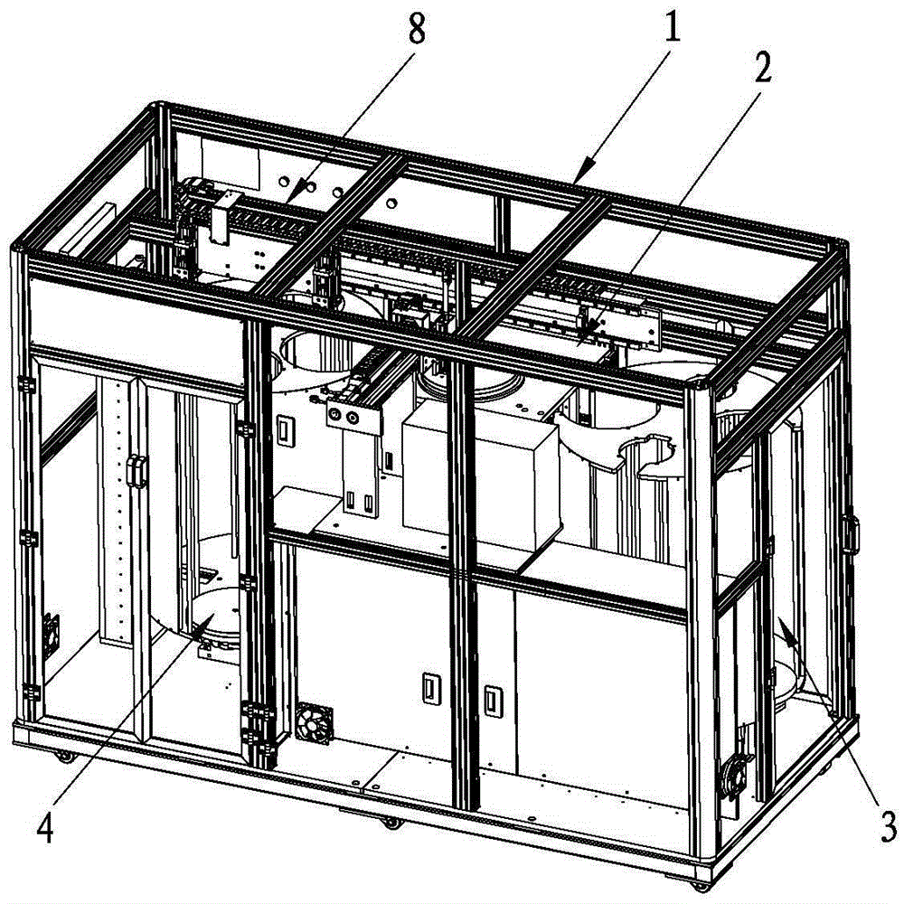
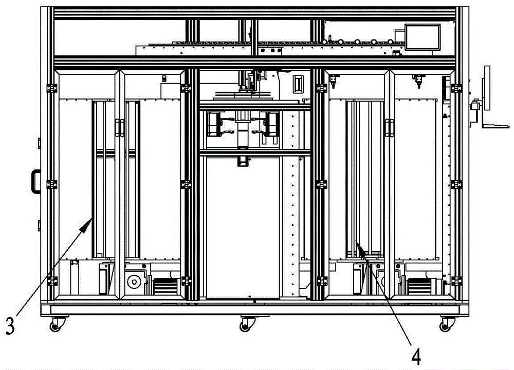
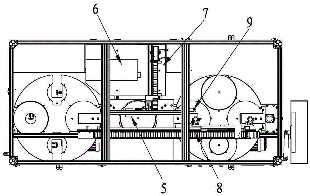
[0050] see Figure 1 to Figure 8, a material identification device, comprising a support frame 1, the support frame 1 is provided with a working platform 2, one side of the working platform 2 is provided with a feeding device 3, and the other side of the working platform 2 is provided with an unloading A material device 4, the top of the working platform 2 is provided with a scanning device 5 for obtaining the identification information of the tray, and the support frame 1 is also provided with a printing device 6, which acquires the identification of the printing device 6 and attaches the identification to the tray The attaching device 7 further includes a conveying device 8 for transferring the tray of the loading device 3 to the working platform 2 and sending the tray of the working platform 2 to the unloading device 4 . When the material identification equipment is working, a number of trays are first installed on the feeding device 3, and then the trays are automatically ...

Embodiment 2

[0064] see Figure 9 , the difference between this embodiment and Embodiment 1 is that the conveying device 8 includes a first linear module 88 and a second linear module 89, and the first linear module 88 is connected with a The material tray of the device 3 is transferred to the first manipulator 85 of the working platform 2 , and the second linear module 89 is connected to the second manipulator 86 for sending the material tray of the working platform 2 to the unloading device 4 . When loading is required, the first linear module 88 drives the first manipulator 85 to move back, the first manipulator 85 acquires the tray and sends the tray to the working platform 2, and when unloading, the second The linear module 89 moves back and drives the second manipulator 86 to obtain the material tray on the working platform 2, and then send the working material tray with the new logo to the unloading device 4. The first linear module and the second linear module 89 are controlled in...


PUM


Abstract

The invention relates to the technical field of identification equipment, and in particular, discloses material identification equipment. The material identification equipment comprises a support frame; a working platform is arranged on the support frame; a loading device is arranged at one side of the working platform; an unloading device is arranged at the other side of the working platform; a scanning device for obtaining identification information of a tray is arranged above the working platform; and the support frame is additionally provided with a printing device, and an attaching device for obtaining a mark of the printing device and attaching the mark on the tray. The material identification equipment further comprises a conveying device for conveying the tray of the loading device to a working platform and sending the tray of the working platform to the unloading device. The equipment can realize automatic mark replacement, is high in working efficiency, precise in identification and excellent in attaching quality, and obviously reduces the labor intensity of operators. The invention further provides a control method of the material identification equipment; and the control method can improve the material warehousing efficiency, is high in attaching accuracy, and preferably prevents the attachment missing phenomenon.

Description

technical field [0001] The invention relates to the technical field of marking equipment, in particular to a material marking device and a control method for the material marking device. Background technique [0002] In the PCB manufacturing process, relatively simple PCB boards also contain dozens of corresponding electronic components (such as capacitors, resistors, transformers, etc.), while more complex PCB boards carry hundreds of electronic components. Electronic components are usually packaged in the form of tapes before they are assembled, and several components are packaged in sequence on a tape, and then the tape is wound on a reel, which facilitates transportation and storage. [0003] However, these reels are provided by different suppliers, and different suppliers and different components will be marked on the reels respectively, and when these reels with different marks enter the assembly factory, it is necessary to re-adapt to these marks for the convenience o...

Claims


Application Information

Patent Timeline
Patent Type & Authority Applications(China)
IPC IPC(8): B65C9/14B65C9/26B65C9/02
CPCB65C9/02B65C9/14B65C9/26
Inventor 吴章华
Owner CELESTICA DONGGUAN SSL TECH LTD
Why Eureka
Try Eureka