Shaft replacing device used for photovoltaic welding strip collecting machine and photovoltaic welding strip collecting machine

A photovoltaic welding ribbon and wire take-up machine technology, which is applied in the directions of transportation and packaging, delivery of filamentous materials, thin material processing, etc., can solve problems affecting production efficiency, machine shutdown, cumbersome operation, etc., to avoid position placement errors, The effect of avoiding machine downtime and improving production efficiency

Active Publication Date: 2016-03-23
SUZHOU YOURBEST NEW TYPE MATERIALS
View PDF15 Cites 5 Cited by
  • Summary
  • Abstract
  • Description
  • Claims
  • Application Information

AI Technical Summary

Problems solved by technology

Since the welding ribbon needs to be rewound and changed continuously, the operation of changing the shaft manually is very cumbersome and time-consuming, and in the process of changing the shaft manually, it is easy to cause the machine to stop due to the misalignment of the shaft position, and also will affect the overall production efficiency

Method used


Image

  • Shaft replacing device used for photovoltaic welding strip collecting machine and photovoltaic welding strip collecting machine
  • Shaft replacing device used for photovoltaic welding strip collecting machine and photovoltaic welding strip collecting machine
  • Shaft replacing device used for photovoltaic welding strip collecting machine and photovoltaic welding strip collecting machine

Examples


Embodiment Construction

[0045] Preferred embodiments of the present invention will be described in detail below in conjunction with the accompanying drawings.

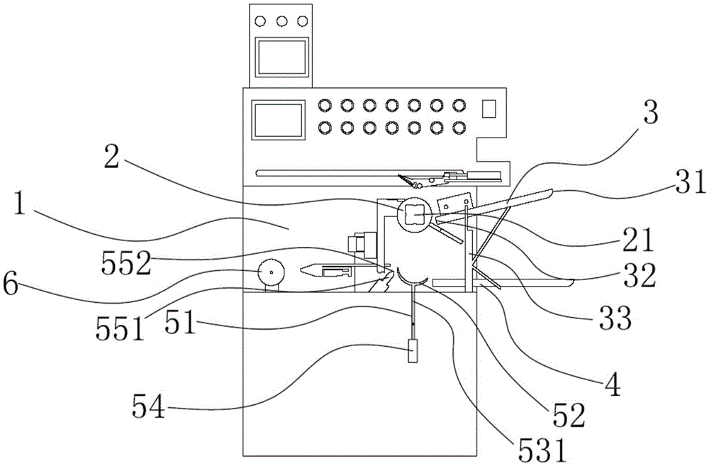
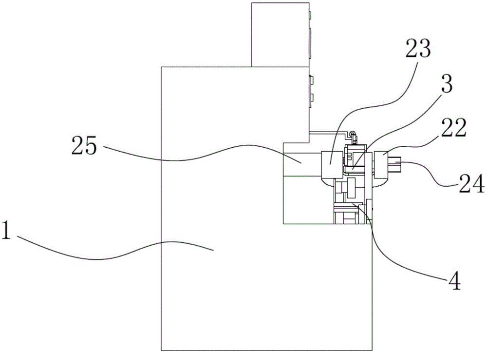
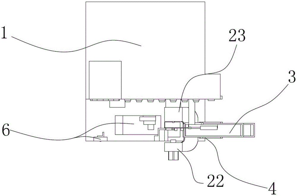
[0046] In order to achieve the purpose of the present invention, as Figure 1-4 As shown, in some embodiments of the shaft changing device applied to the photovoltaic ribbon take-up machine of the present invention, it includes: a clamping and rotating mechanism 2, which is installed on the photovoltaic ribbon take-up machine, and the clamping and rotating mechanism 2. Clamping and circumferential rotation are driven by the first drive unit 21. The clamp rotating mechanism 2 clamps the I-shaped shaft and drives the I-shaped shaft to rotate in the circumferential direction; Arranged obliquely from high to low, the discharge end 32 is connected to the fixture rotation mechanism 2; the discharge mechanism 4 is horizontally arranged and fixed below the feed mechanism 3; the lifting mechanism 5 is driven by the second drive unit 51 Drive to move ...


PUM


Abstract

The invention discloses a shaft replacing device used for a photovoltaic welding strip collecting machine. The shaft replacing device comprises a clamping and rotating mechanism, a feeding mechanism, a discharging mechanism and a lifting mechanism, wherein the clamping and rotating mechanism is mounted on the photovoltaic welding strip collecting machine and driven by a first driving unit to clamp and rotate along the circumference; the clamping and rotating mechanism is used for clamping an I-shaped shaft and drives the I-shaped shaft to rotate along the circumference; the feeding end of the feeding mechanism is obliquely arranged from high to low towards the discharging end; the discharging end of the feeding mechanism is communicated with the clamping and rotating mechanism; the discharging mechanism is horizontally arranged and fixedly arranged under the feeding mechanism; the lifting mechanism is driven by a second driving unit to move to and fro between the clamping and rotating mechanism and the discharging mechanism along the vertical direction, so the I-shaped shaft is conveyed from the clamping and rotating mechanism to the discharging mechanism. The invention also discloses a photovoltaic welding strip collecting machine which comprises the shaft replacing device used for a photovoltaic welding strip collecting machine. Compared with the prior art, the shaft replacing device used for a photovoltaic welding strip collecting machine has the advantages that the manual shaft replacing mode is completely eliminated, and the placement position error and the machine halt are avoided, so the whole production efficiency is improved.

Description

technical field [0001] The invention relates to the technical field of photovoltaic ribbon take-up machines, in particular to a shaft changing device applied to photovoltaic ribbon take-up machines and the photovoltaic ribbon take-up machine. Background technique [0002] Photovoltaic ribbon take-up machine is a commonly used equipment in photovoltaic ribbon processing. Its main function is to wind the ribbon on the I-shaped shaft after the ribbon is processed. [0003] In the current photovoltaic ribbon take-up machine, workers need to manually install the I-shafts one by one on the rotating drive shaft of the photovoltaic ribbon take-up machine, and then start the machine to drive the rotating drive shaft to rotate with the I-shaft. Ribbon rewinding. Since the welding ribbon needs to be rewound and changed continuously, the operation of changing the shaft manually is very cumbersome and time-consuming, and in the process of changing the shaft manually, it is easy to cause...

Claims


Application Information

Patent Timeline
Patent Type & Authority Applications(China)
IPC IPC(8): B65H67/04
CPCB65H67/04
Inventor 肖锋俞永金
Owner SUZHOU YOURBEST NEW TYPE MATERIALS
Why Eureka
Try Eureka