Welding and overturning device for crane beam

A technology of overturning device and crane girder, which is applied in the direction of hoisting device, auxiliary device, hoisting device, etc., can solve the problems of collision between crane girder and overturning device, inconvenient fixing of crane girder, sliding friction of crane girder, etc., and achieve protection of overturning device, Simple structure, avoiding the effect of sliding friction

Inactive Publication Date: 2016-03-23
HENAN SINOKO CRANES
View PDF7 Cites 6 Cited by
  • Summary
  • Abstract
  • Description
  • Claims
  • Application Information

AI Technical Summary

Problems solved by technology

[0002] With the development of industrialization, the application of hoisting machinery in industry is becoming more and more common, the technological update of hoisting machinery is also getting faster and faster, the tonnage of hoisting is getting bigger and bigger, and the production requirements of hoisting machinery are getting more and more High, in the production process of the crane, the left and right webs and cover plates of the crane girder need to be welded together. In order to facilitate the welding operation, it is necessary to turn the web and cover plates at a certain angle to facilitate the welding operation. However, at present There are many inadequacies in the overturning form of the existing overturning device. When different types of beams are welded in the existing overturning device, it is easy to cause the girder to slide during the overturning process, causing the impact of the crane beam and the overturning device, which is easy to cause the overturning device to fail. In addition, during the overturning process, the crane girder is prone to sliding friction with the overturning device, causing damage. In addition, the overturning angle cannot be overturned according to different crane girder models, and it cannot be adjusted to the best angle for welding. Finally, After adjusting the angle, it is inconvenient to fix the crane girder. The usually used compression method may easily cause the web on the unwelded side to bear a large external force, which may easily cause the crane girder to deform.

Method used


Image

  • Welding and overturning device for crane beam
  • Welding and overturning device for crane beam
  • Welding and overturning device for crane beam

Examples


Embodiment 1

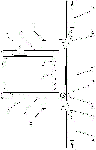
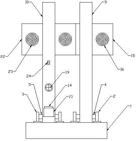
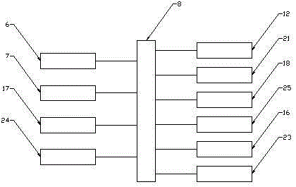
[0019] Such as Figure 1-3 As shown, a crane girder welding overturning device includes a base 1, and the upper surface of the base 1 is symmetrically provided with a support A2 and a support B3, and the bearings in the support A2 and the support B3 are A rotating shaft A4 and a rotating shaft B5 are respectively provided, and the ends of the rotating shaft A4 and the rotating shaft B5 are respectively connected with an angle sensor A6 and an angle sensor B7, and the angle sensor A6 and the angle sensor B7 are connected with a controller 8 , the middle part of the rotating shaft A4 and the rotating shaft B5 is respectively connected with an overturning frame A9 and an overturning frame B10, the described overturning frame A9 is arranged as an L-shaped structure, and the bending part of the overturning frame A9 is connected with an overturning push rod A11, and the described The end of overturning push rod A11 is hingedly connected with hydraulic cylinder A12, and the upper sur...

Embodiment 2

[0022] Such as Figure 1-3 As shown, a crane girder welding overturning device includes a base 1, and the upper surface of the base 1 is symmetrically provided with a support A2 and a support B3, and the bearings in the support A2 and the support B3 are A rotating shaft A4 and a rotating shaft B5 are respectively provided, and the ends of the rotating shaft A4 and the rotating shaft B5 are respectively connected with an angle sensor A6 and an angle sensor B7, and the angle sensor A6 and the angle sensor B7 are connected with a controller 8 , the middle part of the rotating shaft A4 and the rotating shaft B5 is respectively connected with an overturning frame A9 and an overturning frame B10, the described overturning frame A9 is arranged as an L-shaped structure, and the bending part of the overturning frame A9 is connected with an overturning push rod A11, and the described The end of overturning push rod A11 is hingedly connected with hydraulic cylinder A12, and the upper sur...


PUM


Abstract

The invention relates to a welding and overturning device for a crane beam. The welding and overturning device comprises a base. A hydraulic cylinder A and a hydraulic cylinder B are hinged to the two ends in the base. The hydraulic cylinder A and the hydraulic cylinder B are connected with an overturning frame A and an overturning frame B in a hinged manner respectively. Rolling seats are arranged on the upper surfaces of horizontal supports of the overturning frame A and the overturning frame B. A supporting plate A is arranged on the upper portion of a vertical support of the overturning frame A. An electromagnet A is arranged on the rear side face of the supporting plate A. A contact switch A is arranged in the middle of the overturning frame A. One side of the lower portion of the overturning frame A is connected with an electric push rod A. A rolling seat is arranged on the upper surface of a horizontal support of the overturning frame B. A rotating roller is arranged in the rolling seat. A supporting plate B is arranged on the upper portion of a vertical support of the overturning frame B. An electromagnet B is arranged on the rear side face of the supporting plate B. A contact switch B is arranged in the middle of the overturning frame B. An electric push rod B is connected with one side of the lower portion of the overturning frame B. The welding and overturning device has the beneficial effects that the structure is simple, use and operation are convenient, and design is reasonable.

Description

technical field [0001] The invention belongs to the technical field of hoisting machinery auxiliary equipment, in particular to a crane girder welding turning device. Background technique [0002] With the development of industrialization, the application of hoisting machinery in industry is becoming more and more common, the technological update of hoisting machinery is also getting faster and faster, the tonnage of hoisting is getting bigger and bigger, and the production requirements of hoisting machinery are getting more and more High, in the production process of the crane, the left and right webs and cover plates of the crane girder need to be welded together. In order to facilitate the welding operation, it is necessary to turn the web and cover plates at a certain angle to facilitate the welding operation. However, at present There are many inadequacies in the overturning form of the existing overturning device. When different types of beams are welded in the existin...

Claims


Application Information

Patent Timeline
Patent Type & Authority Applications(China)
IPC IPC(8): B66F19/00B23K37/047
CPCB66F19/00B23K37/047
Inventor 胡哲涛王积贤崔丽范武军
Owner HENAN SINOKO CRANES
Why Eureka
Try Eureka