A working method for stabilizing a vehicle-mounted tent
A working method and vehicle-mounted technology, applied in tents/canopies, building types, buildings, etc., can solve the problems of unstable use process, nowhere to store the inflatable support frame, occupying space, etc., to achieve the effect of ensuring stability
- Summary
- Abstract
- Description
- Claims
- Application Information
AI Technical Summary
Problems solved by technology
Method used
Image
Examples
Embodiment 1
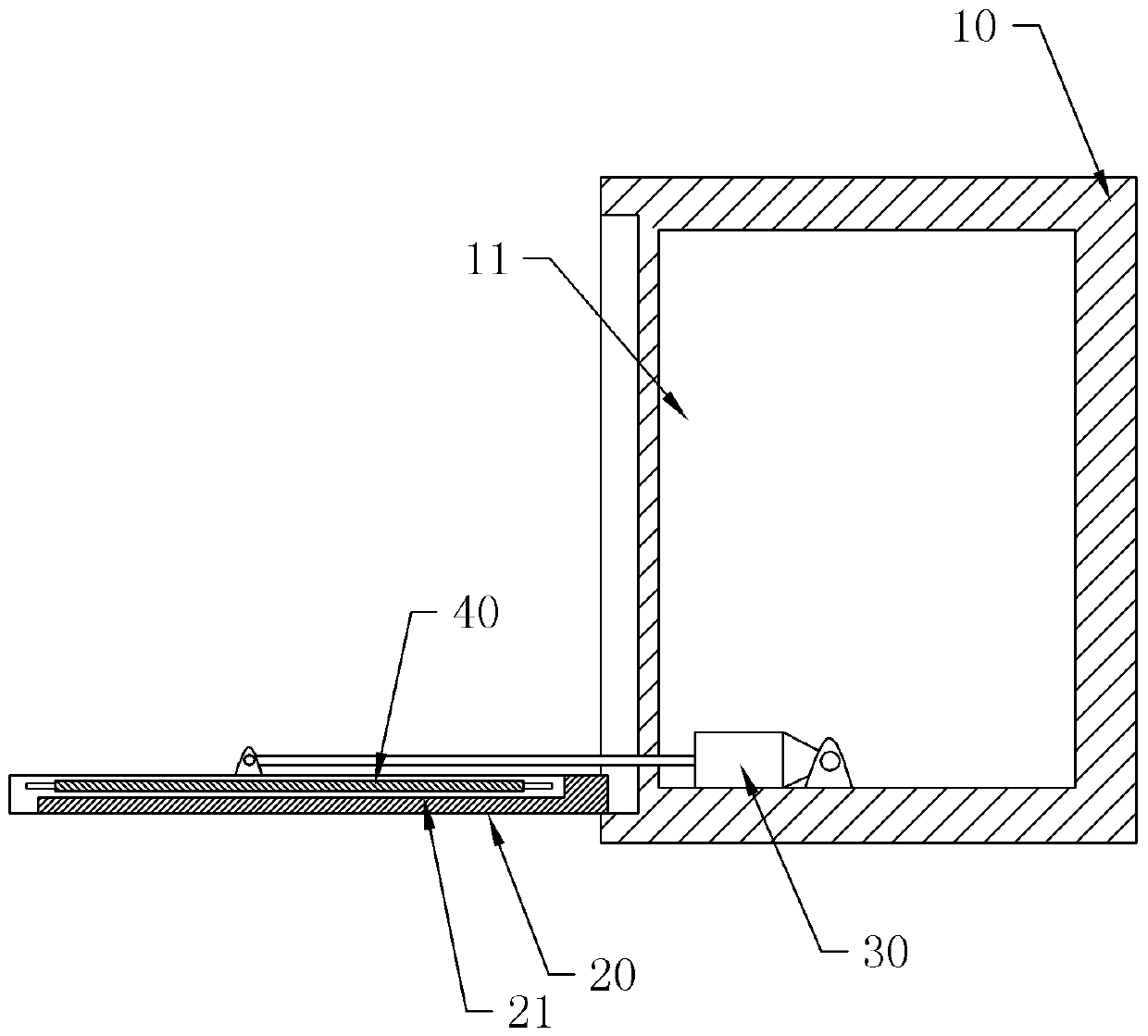
[0025] The embodiment is basically as attached figure 1 Shown: a working method for stabilizing a vehicle-mounted tent. The vehicle-mounted tent includes a base plate 20, an inflatable support frame, a tarpaulin and a folding mechanism. One side of the base plate 20 is hinged to the lower part of one side of the carriage 10, and the base plate 20- A first storage slot 11 is formed on the outer wall of the compartment 10 on the side, and a second storage slot 21 is provided on the base plate 20. The base plate 20 is provided with a support plate 40 that is slidably connected with it and can cover the second storage slot 21. The board 40 is also welded with ladder steps for users to go up and down. The sliding direction of the sliding connection is perpendicular to the straight direction of the car, and the supporting board 40 can slide to the edge of the bottom board 20 and turn over; the inflatable support frame is connected in the second receiving groove 21, and The tarpaulin...
Embodiment 2
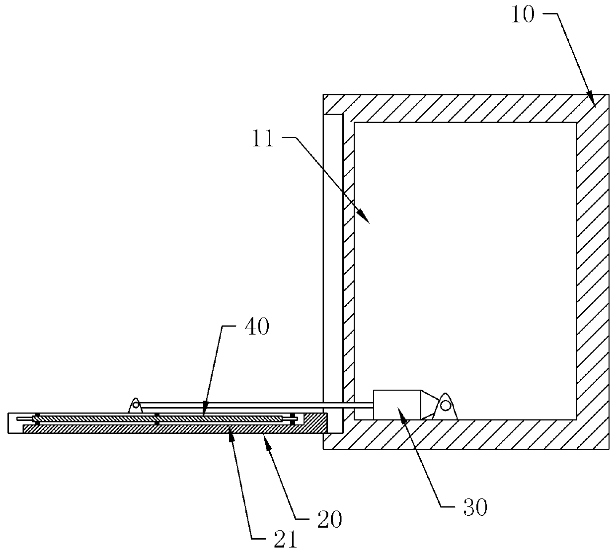
[0033] like figure 2 As shown, the difference from Embodiment 1 is that: the second receiving groove 21 is internally threaded with a winding column 50 arranged along the circumferential direction of the second receiving groove 21 .
[0034] Step 4 also includes the step of winding the inflatable support frame on the winding column after the inflatable support frame is deflated. After the inflatable support frame is deflated, the inflatable support frame is wound on the winding column, so that the folded inflatable support frame can be more orderly, avoid mutual entanglement, and be convenient for next use.
Embodiment 3
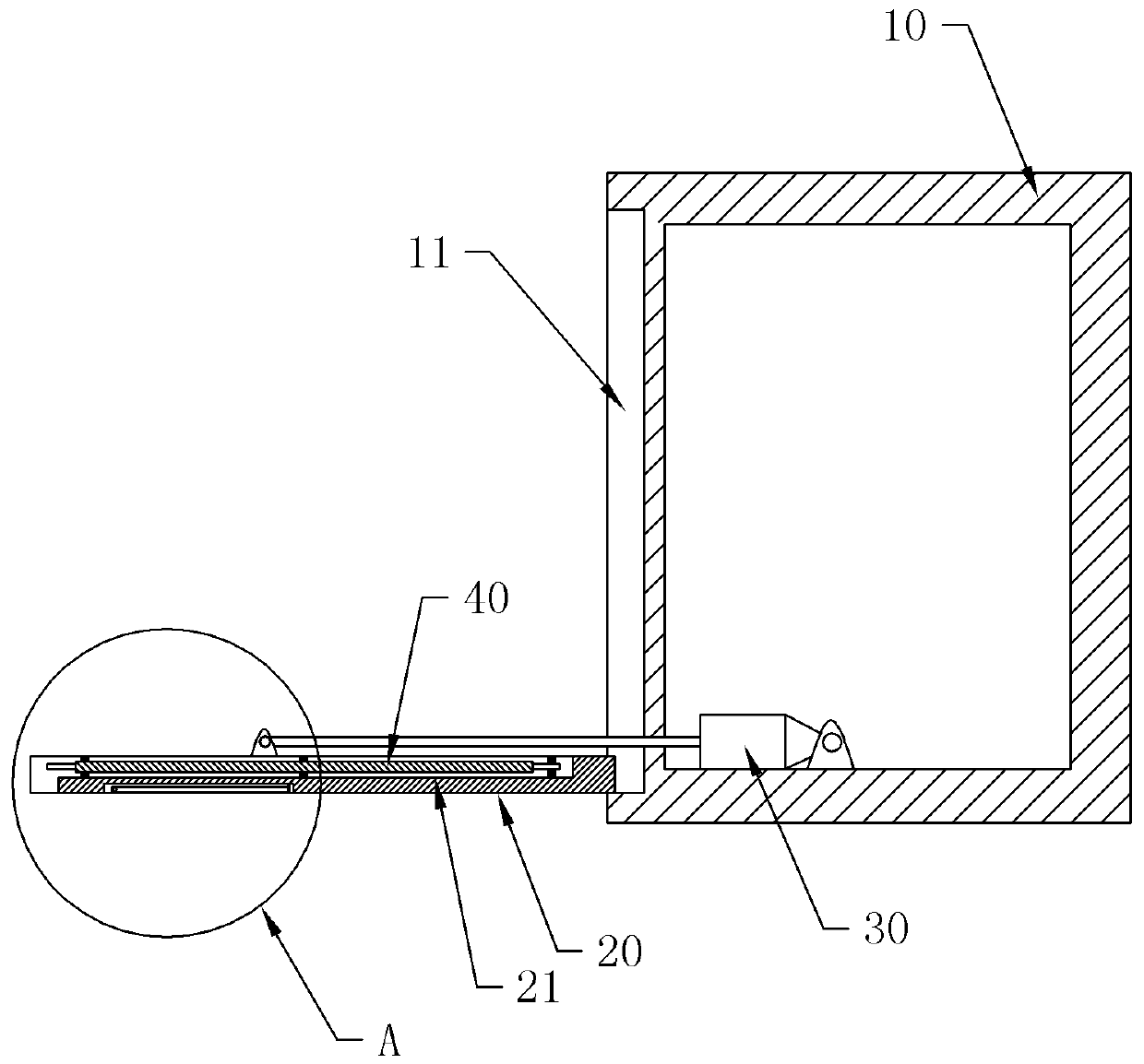
[0036] like image 3 and Figure 4 As shown, the difference from Embodiment 2 lies in that: a plurality of installation slots 60 are defined on the outside of the bottom plate 20 , and a supporting leg 70 is hinged in each installation slot 60 .
[0037] After step 3, the following step is also included: unfolding the supporting legs 70 in the installation groove 60 and supporting them on the ground. After the support plate 40 is opened, the support leg 70 in the installation groove 60 is opened, so that the support leg 70 is supported on the ground, and the support plate 40 is supported by the support leg 70, which can ensure the force balance of the support plate 40.
PUM
 Abstract
Description
Claims
Application Information
 - R&D
- Intellectual Property
- Life Sciences
- Materials
- Tech Scout
- Unparalleled Data Quality
- Higher Quality Content
- 60% Fewer Hallucinations
Browse by: Latest US Patents, China's latest patents, Technical Efficacy Thesaurus, Application Domain, Technology Topic, Popular Technical Reports.
© 2025 PatSnap. All rights reserved.Legal|Privacy policy|Modern Slavery Act Transparency Statement|Sitemap|About US| Contact US: help@patsnap.com


