
Extendible shelter

a shelter and extension technology, applied in the field of extension shelters, can solve the problems of cumbersome extension or retracting, difficult to obtain maximum retracting cover for the retracting configuration of the shelter, and difficulty in extending or retracting the cover on the frame, so as to achieve easy extension and retracting, easy and releasable anchoring

Inactive Publication Date: 2011-07-19
AHMEDY HAMIDULLAH
View PDF29 Cites 18 Cited by
  • Summary
  • Abstract
  • Description
  • Claims
  • Application Information

AI Technical Summary

Benefits of technology

"The present invention provides an improved extendible shelter for a building. The shelter can be easily extended and retracted, and the cover of the shelter automatically extends and retracts with the frame of the shelter. The shelter can be extended or retracted to different lengths relative to the building. The shelter can be easily and releasably anchored to a ground surface. The shelter includes a frame and a plurality of extendible and retractable covers connected to the frame. The covers are fixedly connected to each other with fasteners that can be unfixed and refixed as the shelter is extended or retracted. The fasteners are zippers with interlocking teeth that are fixed and unfixed by a slider. The technical effects of the invention include improved flexibility, ease of use, and durability of the shelter."

Problems solved by technology

Unfortunately, shelters such as those discussed above present a number of disadvantages.
Firstly, they may be cumbersome to extend or retract, and may require more than one person to effect extension and retraction thereof.
Further, extension and retraction of the cover on the frame may be difficult.
In particular, with the cover connected to and extending between each extendible support section, obtaining maximal retraction of the cover for the retracted configuration of the shelter may be difficult.

Method used


Image

  • Extendible shelter
  • Extendible shelter
  • Extendible shelter

Examples


Embodiment Construction

[0027]With reference to the annexed drawings the preferred embodiments of the present invention will be herein described for indicative purpose and by no means as of limitation.

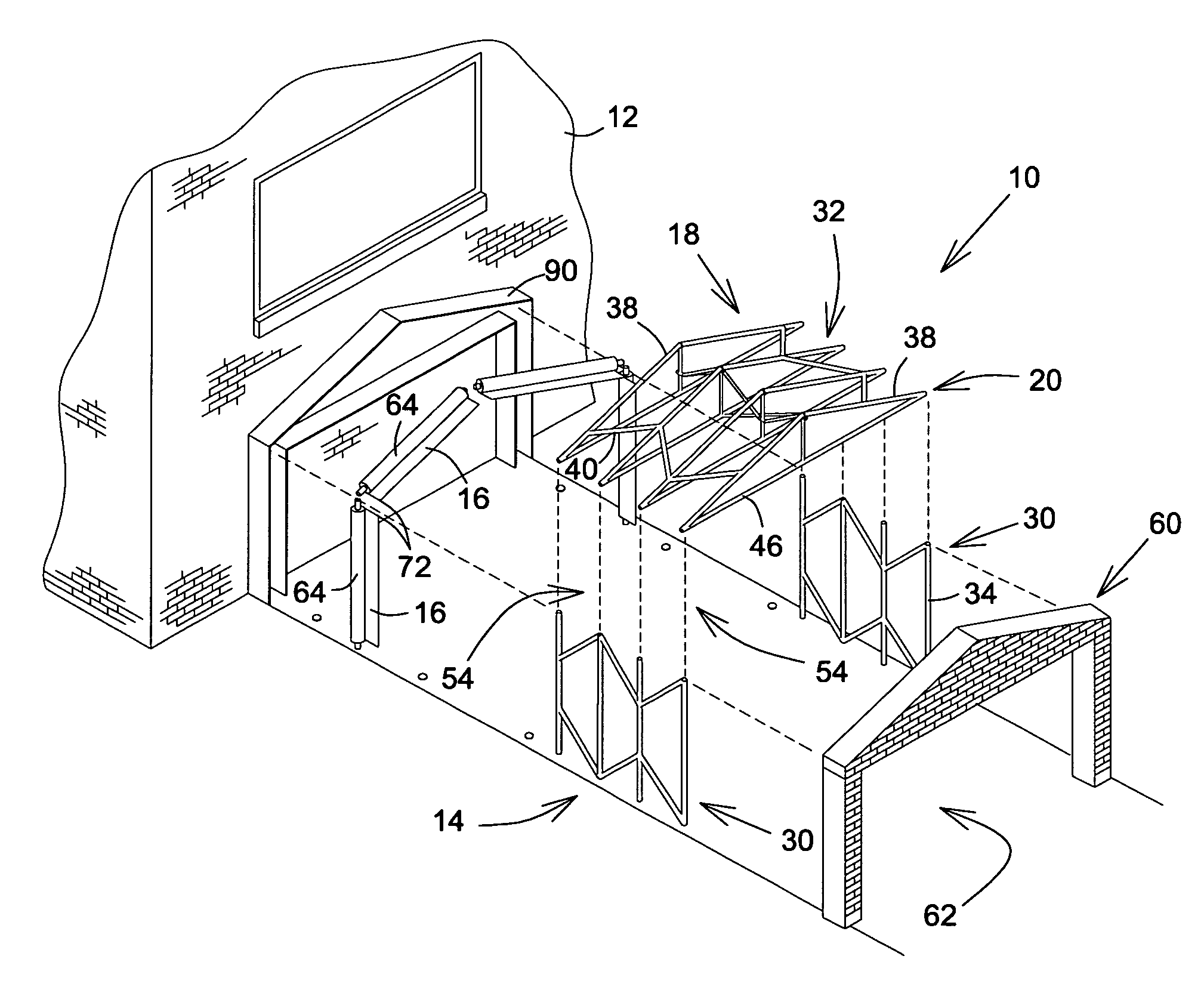
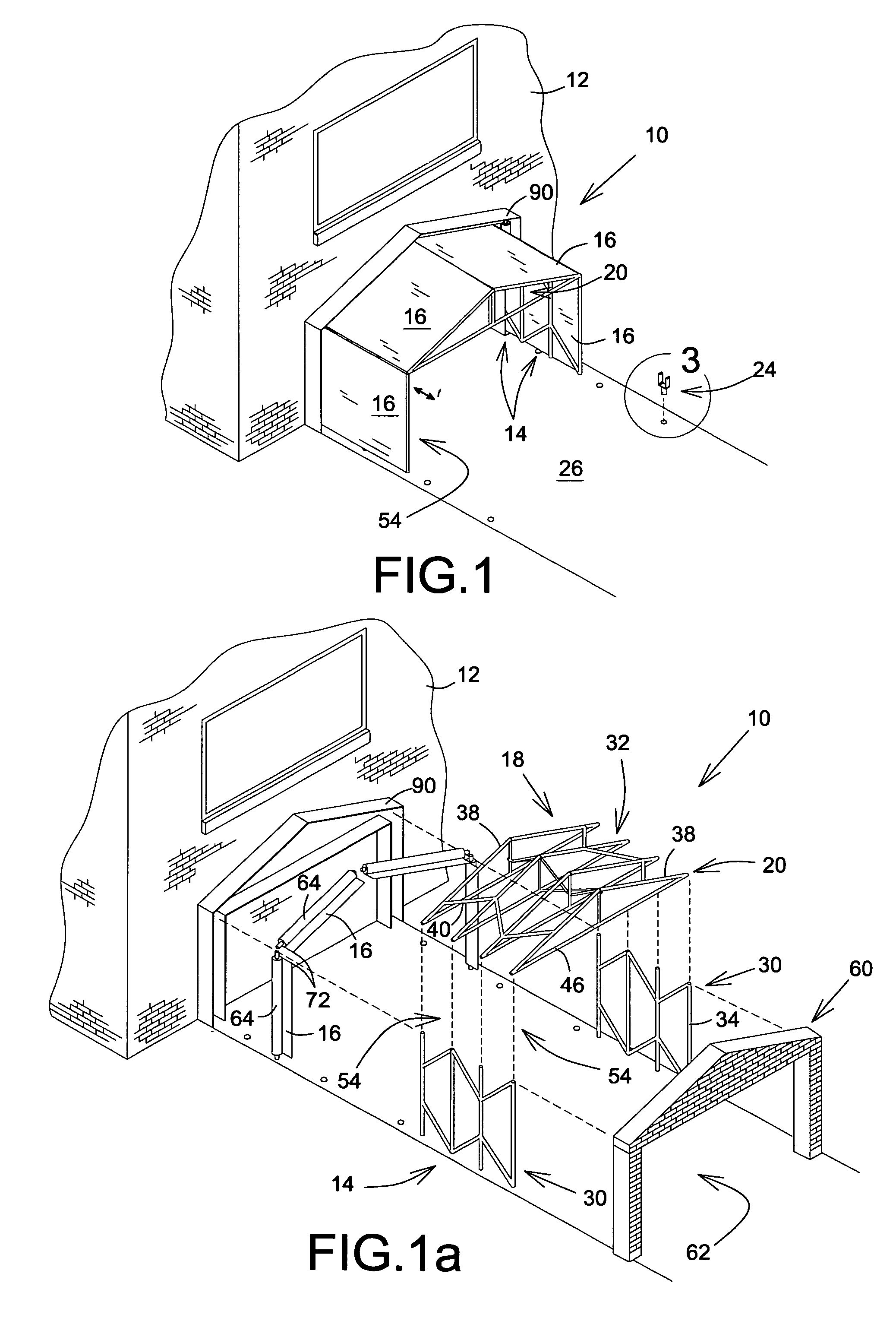
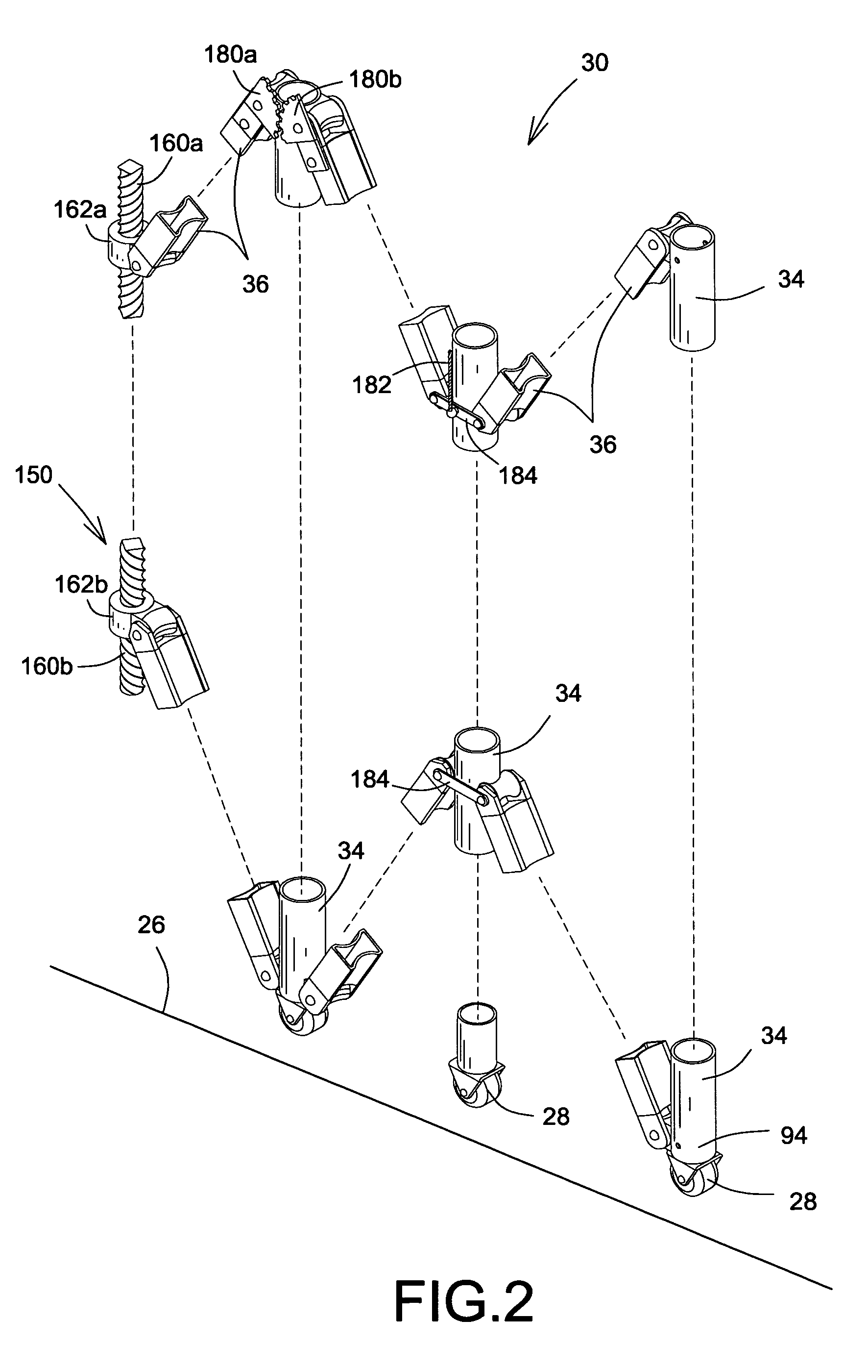
[0028]Referring to FIGS. 1, 1a, 2, 3, 4, 5, 6, and 7 there is shown an embodiment of an extendible shelter, shown generally as 10, for a building 12 in accordance with an embodiment of the present invention. As best shown In FIGS. 1 and 1a, the shelter 10 has an extendible and retractable frame, shown generally as 14, a plurality of extendible and retractable covers 16 connected to the building 12 and to the frame 14. The frame 14 is connected to the building on an innermost frame end thereof, shown generally as 18 and situated proximal the building 12, with the covers 16 connected to an outermost frame end, shown generally as 20, situated generally longitudinally opposite the innermost frame end 18 and generally distal the building 12. A plurality of fasteners 70, best shown in FIG. 5, fasten and unfasten ad...


PUM


Abstract

An extendible shelter connectable to a building has an extendible frame and a plurality of covers, connected to an outermost frame end, for covering the frame. Adjacent covers are connected to one another at outermost edge ends of their adjacent edges, which are threaded through a fastener. As the frame is extended outwardly away from the building, the adjacent edges are drawn through the fastener, which fastens the edges together to automatically fasten the adjacent covers. When the frame is retracted, the fastener unfastens the edges and covers. Anchor for locking wheels for the frame in fixed position on a ground surface over which the shelter extends are also disclosed.

Description

FIELD OF THE INVENTION[0001]The present invention relates to shelters, and is more particularly directed to an extendible shelter for connection to a building.BACKGROUND OF THE INVENTION[0002]Extendible shelters for buildings are well known in the art. Such shelters typically have an extendible frame, or truss, and a covering, both of which are connectable on an innermost shelter end of the shelter to the building. The frame and cover, notably outermost ends thereof, are extendible away from and retractable towards the building to enable extension and retraction of the shelter. The outermost end of the shelter typically has an access aperture disposed therein to allow entry and exit from the shelter when extended. The sizes of the shelters are variable and may allow for entry and exit, as well as storage, of equipment or vehicles therein.[0003]For example, U.S. Pat. No. 5,839,462 issued to Randall on Nov. 24, 1998, teaches an expandable shelter having an expandable support frame hav...

Claims


Application Information

Patent Timeline
Patent Type & Authority Patents(United States)
IPC IPC(8): E04B1/34E04H15/50E04B1/346E04B7/16E04H1/00E04H15/18E04H15/34E04H15/48
CPCE04H3/165E04H15/52
Inventor AHMEDY, HAMIDULLAH
Owner AHMEDY HAMIDULLAH
Learn More