Combined type sealing device for liquid oxygen pump

A technology of sealing device and liquid oxygen pump, which is applied in the direction of engine sealing, engine components, mechanical equipment, etc., can solve the problems of large leakage, friction pair wear, medium leakage, etc., and achieve good axial and angular compensation, Excellent sealing performance to achieve zero wear effect

Active Publication Date: 2016-03-23
XIAN AEROSPACE PROPULSION INST
View PDF10 Cites 11 Cited by
  • Summary
  • Abstract
  • Description
  • Claims
  • Application Information

AI Technical Summary

Problems solved by technology

[0002] As an important part of the liquid rocket engine, the liquid oxygen pump is used to deliver the low-temperature liquid oxygen required for the engine to work. Since the liquid oxygen pump usually works at a very high speed, and the liquid oxygen is easy to vaporize, it is necessary to supply the liquid oxygen The seal design of the pump brings extremely high challenges. At present, there are mainly two types of seals: one is to set a disengagement mechanical seal at the inlet of the liquid oxygen pump. The opening gap is on the order of millimeters, so it will cause a large amount of medium leakage and reduce the working efficiency of the liquid oxygen pump; the other is to install a contact mechanism at the inlet of the liquid oxygen pump. The high-speed friction of the end face will cause serious wear of the friction pair, and the leakage of the seal will increase sharply, which will affect the working life and reusability of the engine
[0003] Based on the above, it can be seen that the existing sealing technology of liquid oxygen pumps has the disadvantages of large leakage or severe wear of friction pairs.

Method used


Image

  • Combined type sealing device for liquid oxygen pump
  • Combined type sealing device for liquid oxygen pump
  • Combined type sealing device for liquid oxygen pump

Examples


Embodiment Construction

[0034] The following is attached Figure 1~3 The specific implementation shown will further describe the above content of the present invention in detail. However, it should not be construed that the scope of the above-mentioned subject matter of the present invention is limited only to the following examples. Without departing from the above-mentioned technical idea of ​​the present invention, various replacements or changes made according to common technical knowledge and customary means in this field shall be included in the scope of the present invention.

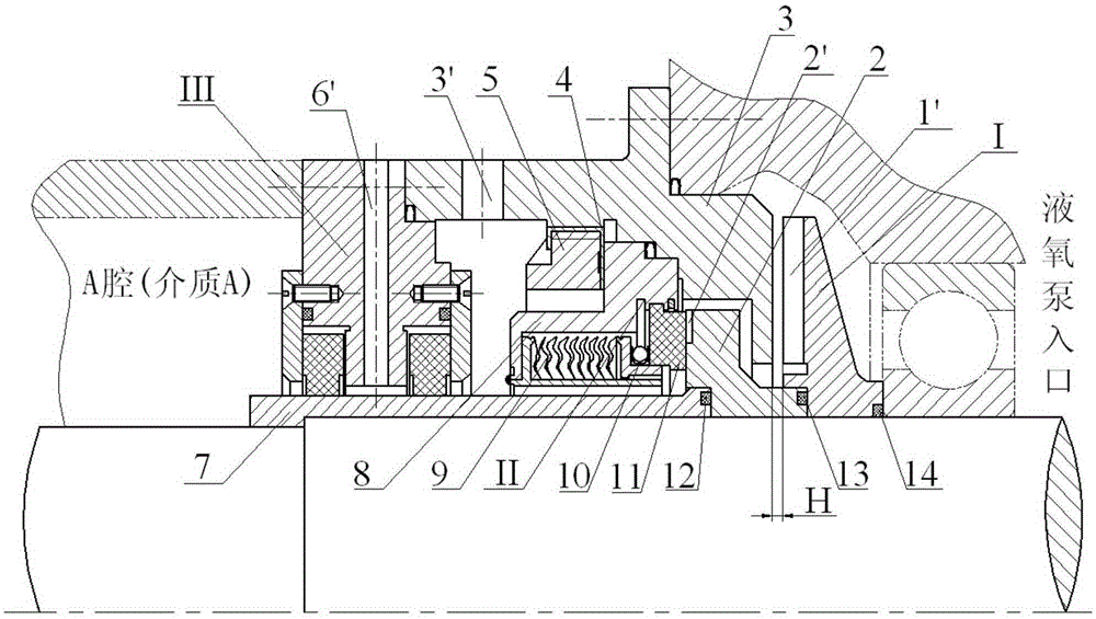
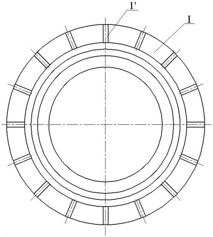
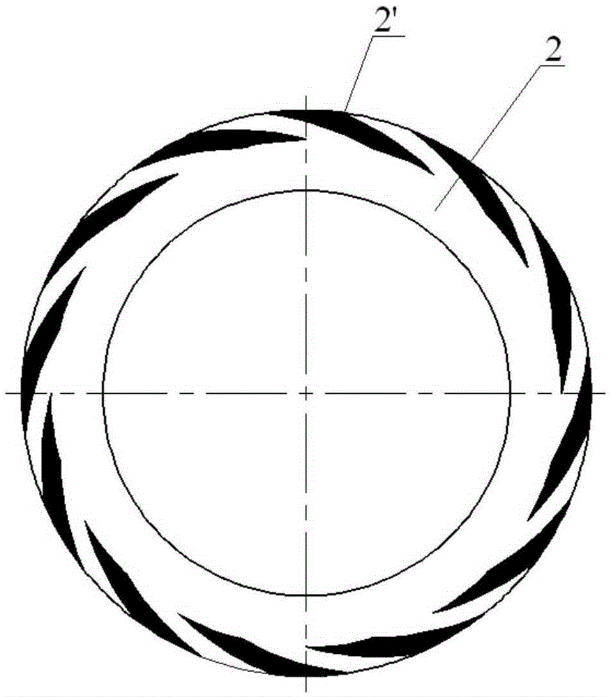
[0035] Such as figure 1 As shown, a combined sealing device for a liquid oxygen pump of the present invention includes three types of non-contact seals arranged in series at the inlet of the liquid oxygen pump, which are respectively a first-level centrifugal seal I, a second-level dry gas seal II, and a third-level seal. Stage floating ring seal III.

[0036] A blade 1' is processed on the primary centrifugal seal I...


PUM


Abstract

The invention discloses a combined type sealing device for a liquid oxygen pump. The combined type sealing device comprises three non-contact seals sequentially arranged in a series-connected mode, namely the first-stage centrifugal seal, the second-stage dry gas seal and the third-stage floating ring seal. Blades of the first-stage centrifugal seal and dynamic pressure grooves of the second-stage dry gas seal are arranged in the same direction and turn the backs to the inlet of the liquid oxygen pump. A sealing cavity is formed among the second-stage dry gas seal, the third-stage floating ring seal and a sealed case, the sealed case is provided with a fluid channel, and the third-stage floating ring seal is provided with another fluid channel. The combined type sealing device well solves the problems that currently the seal faces of the liquid oxygen pump have wear-out failures or the leakage rate is large, and has the advantages of being long in service life and high in reliability.

Description

technical field [0001] The invention relates to the technical field of fluid sealing devices, and is suitable for sealing the inlet of a liquid oxygen pump, especially the inlet sealing of a liquid oxygen pump for a liquid rocket engine. Background technique [0002] As an important part of the liquid rocket engine, the liquid oxygen pump is used to deliver the low-temperature liquid oxygen required for the engine to work. Since the liquid oxygen pump usually works at a very high speed, and the liquid oxygen is easy to vaporize, it is necessary to supply the liquid oxygen The seal design of the pump brings extremely high challenges. At present, there are mainly two types of seals: one is to set a disengagement mechanical seal at the inlet of the liquid oxygen pump. The opening gap is on the order of millimeters, so it will cause a large amount of medium leakage and reduce the working efficiency of the liquid oxygen pump; the other is to install a contact mechanism at the inl...

Claims


Application Information

Patent Timeline
Patent Type & Authority Applications(China)
IPC IPC(8): F16J15/40F16J15/30F16J15/16
CPCF16J15/16F16J15/30F16J15/40
Inventor 张树强陈杰王良赵伟刚郝飞李志宇
Owner XIAN AEROSPACE PROPULSION INST
Why Eureka
Try Eureka