Height-adjustable roller press device

An adjustable, rolling technology, applied in the field of sheet rolling equipment, can solve the problems of easy water leakage, large driving equipment, high use cost, and achieve the effect of easy maintenance, reducing use cost and maintenance cost, and prolonging service life.

Inactive Publication Date: 2015-04-29
CHANGZHOU LONGDAO E COMMERCE
View PDF5 Cites 1 Cited by
  • Summary
  • Abstract
  • Description
  • Claims
  • Application Information

AI Technical Summary

Problems solved by technology

[0003] 1. When the heating press roller is heated by water circulation, first of all, the processing of the circulating water channel inside the heating press roller is difficult, resulting in an increase in the processing cost of the heating press roller. In addition, the circulating water channel inside the heating press roller has high requirements for sealing and is prone to water leakage. Phenomenon, the requirements for rice noodles at each joint are higher;
[0004] 2. When heating rods are installed inside the heating press roller, it is first necessary to install blind holes on the surface of the heating press roller, which affects the integrity of the heating press roller and has an impact on the overall rigidity of the heating press roller. Secondly, the heating press roller The shaft part rotates, and the shaft part is worn out, but after the shaft part is worn out, the entire heating press roller is scrapped and cannot be repaired, resulting in high cost of use
[0005] In addition, the existing heating and pressing rollers generally drive the heating and pressing rollers to move up and down through oil cylinders or air cylinders. When used for large rollers, this requires the bearing capacity of the oil cylinders or air cylinders, resulting in excessive volume of the driving equipment.

Method used


Image

  • Height-adjustable roller press device
  • Height-adjustable roller press device
  • Height-adjustable roller press device

Examples


Embodiment Construction

[0018] The present invention will be further described below in conjunction with the accompanying drawings.

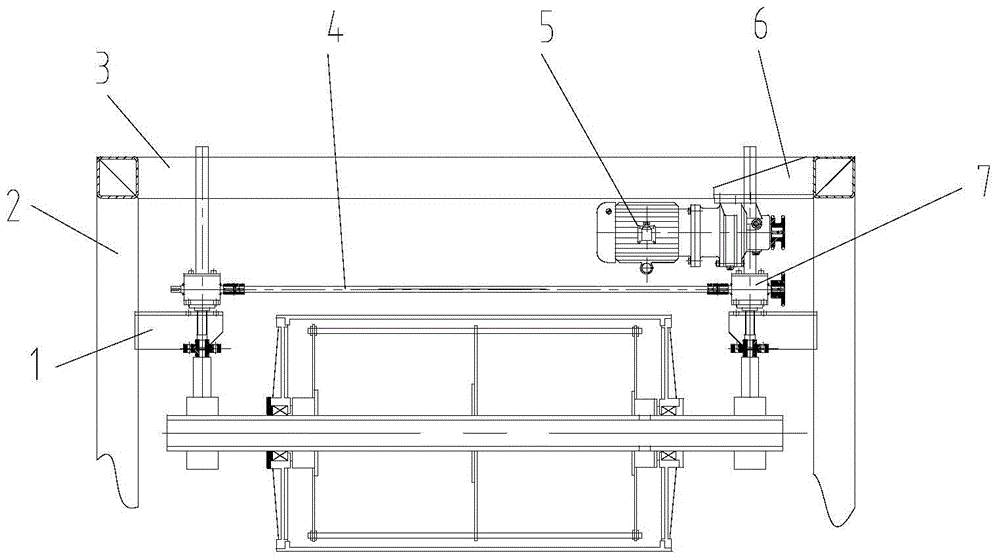
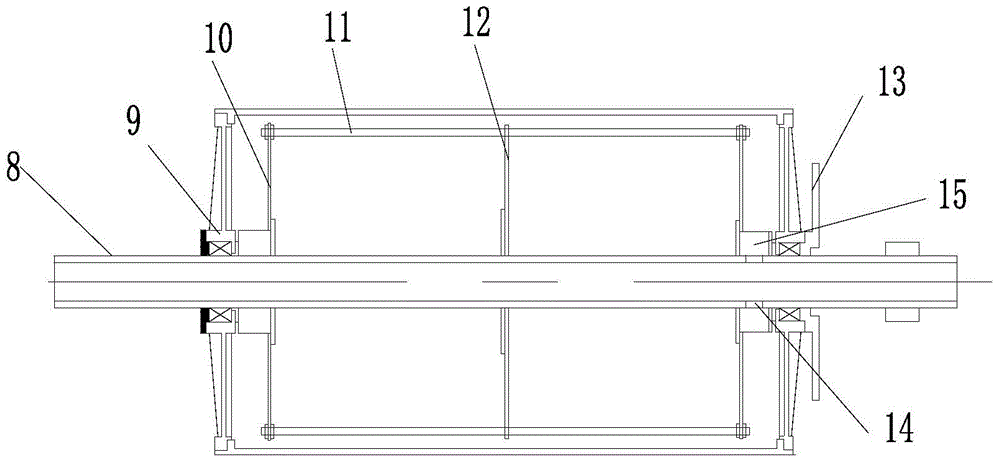
[0019] Such as figure 1 and figure 2 A height-adjustable rolling device is shown, which includes symmetrically arranged vertical brackets, and the top of the vertical brackets is connected with a top bracket. There is a lifting mechanism on the top, and the lower end of the lifting mechanism is connected with a heating pressure roller. The heating pressure roller includes a hollow heating roller shaft. The surface of the heating roller shaft is symmetrically fixed with a set of heating rod fixing brackets. There are not many heating rods arranged along the edges between the brackets, a heating roller is arranged on the outer heating roller shaft of the heating rod fixing bracket, a heat shield is arranged between the heating roller and the heating rod fixing bracket, and the heating rod is fixed A threading hole is provided on the support, and a wire hole correspond...


PUM


Abstract

The invention belongs to board roller press equipment, and particularly relates to a height-adjustable roller press device. The height-adjustable roller press device comprises vertical brackets arranged symmetrically, wherein the top parts of the vertical brackets are connected with a top bracket. The height-adjustable roller press device is characterized in that mounting plates are symmetrically arranged on the inner side surfaces of the vertical brackets, lifting mechanisms are arranged on the mounting plates, a heating press roller is connected to the lower ends of the lifting mechanisms and comprises a hollow thermal roller shaft, a group of heating rod fixing brackets are symmetrically and fixedly arranged on the surface of the heating roller shaft, a plurality of heating rods are uniformly arranged among the heating rod fixing brackets along the edges of the heating rod fixing brackets, thermal rollers are arranged on the thermal roller shaft on the outer side of the heating rod fixing brackets, thermal baffles are arranged between the thermal rollers and the thermal roller shaft, wire penetrating holes are formed in the heating rod fixing brackets, and wire holes corresponding to the wire penetrating holes are formed in the thermal roller shaft and communicated with a hollow part of the thermal roller shaft.

Description

technical field [0001] The invention belongs to plate rolling equipment, in particular to a height-adjustable rolling device. Background technique [0002] The existing heating press roller is generally provided with a circulating water channel in the heating press roller, and the heating press roller is heated by introducing circulating water into the circulating water channel, or a blind hole for installation is provided along the end surface of the side wall of the heating press roller. A heating rod is arranged in the installation blind hole, and the heating pressure roller is heated by heating the heating rod, which has the following problems: [0003] 1. When the heating press roller is heated by water circulation, first of all, the processing of the circulating water channel inside the heating press roller is difficult, resulting in an increase in the processing cost of the heating press roller. In addition, the circulating water channel inside the heating press rolle...

Claims


Application Information

Patent Timeline
Patent Type & Authority Applications(China)
IPC IPC(8): B29C43/46B29C43/24B29C43/52
CPCB29C43/46B29C43/24B29C43/52
Inventor 董春玲
Owner CHANGZHOU LONGDAO E COMMERCE
Why Eureka
Try Eureka