Wet type drilling rotary mechanism

A rotary mechanism, wet technology, used in mechanical equipment, earthwork drilling, drilling equipment, etc., can solve the problems of poor sealing effect, unusable, difficult maintenance, etc., to achieve simple and fast maintenance, improved service life, and good sealing effect. Effect

Pending Publication Date: 2021-01-15
神木市金承机械科技有限公司
View PDF0 Cites 0 Cited by
  • Summary
  • Abstract
  • Description
  • Claims
  • Application Information

AI Technical Summary

Problems solved by technology

Moreover, this structure is easy to cause wear to both the sealing ring and the rotary shaft. After the wear, the rotary mechanism leaks. After the water leaks, the sealing groove is easily corroded and cannot be cleaned, resulting in poor sealing effect after maintenance, greatly shortening the service life.
And because the sealing ring is embedded in the inner groove of the contact surface between the rotary shaft of the slewing mechanism and the housing, it is inconvenient to replace the sealing ring and difficult to overhaul
[0003] The above-mentioned problems lead to the current water leakage of the slewing mechanism of the current bolter miner and cannot be used after about 6 months. It needs to be repaired or replaced.

Method used


Image

  • Wet type drilling rotary mechanism
  • Wet type drilling rotary mechanism
  • Wet type drilling rotary mechanism

Examples


Embodiment Construction

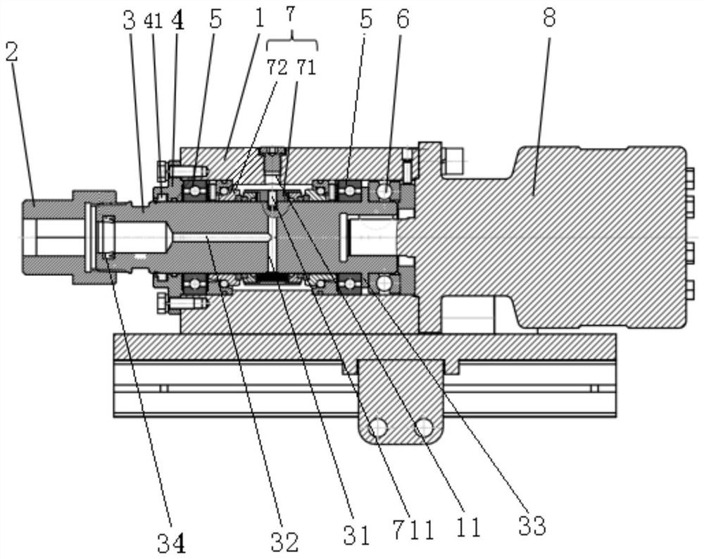
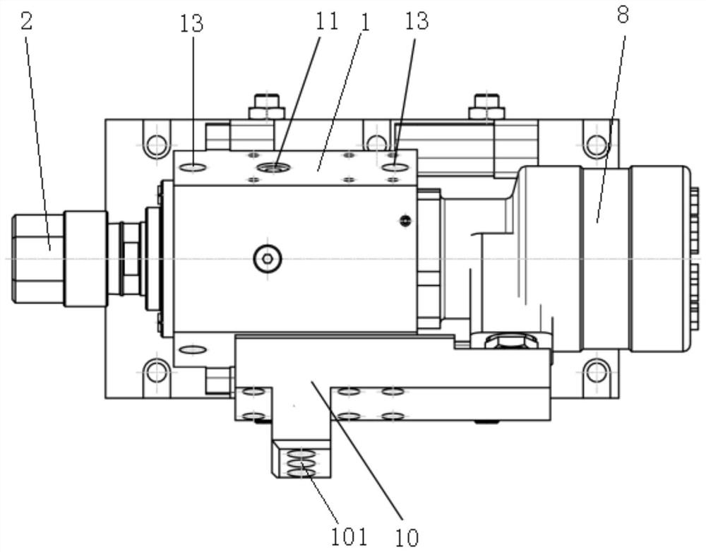
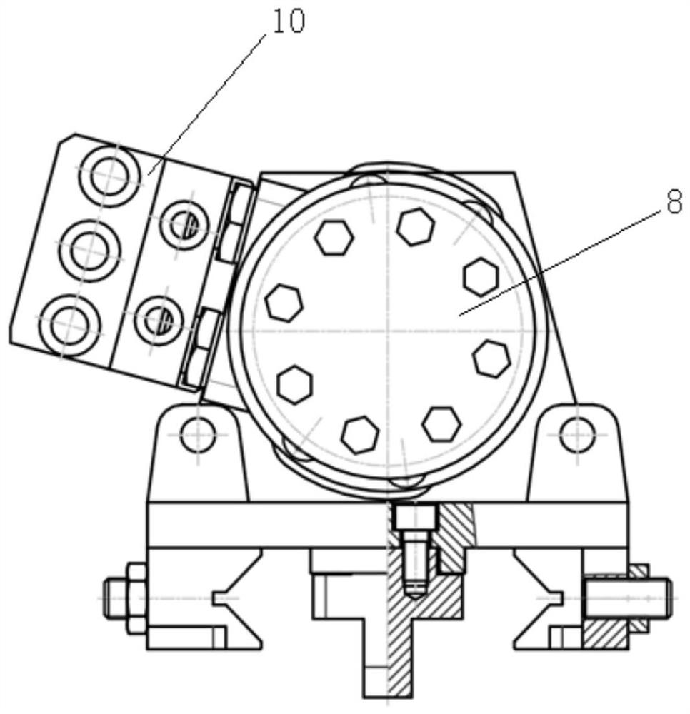
[0021] In order to solve the slewing mechanism of the existing bolter and wet dust removal bolt and cable drilling rig, the existing accessories are not easy to replace during maintenance, the surface precision of the slewing shaft is high during processing, and the casing is corroded after water leakage, resulting in scrap or short service life. etc., the present application provides a JCJM-ZZZX type wet drilling rotary mechanism. Its specific example is as follows.

[0022] Refer to attached Figures 1 to 3 As shown, the wet drilling rotary mechanism of this embodiment includes a casing 1 and a rotary shaft 3 passing through the central through hole of the casing 1. One end of the rotary shaft 3 is connected to the power motor 8 through a spline, and the other end is connected to the shaft nut. 2 connections. The power motor 8 drives the rotary shaft 3 to rotate like this, and the rotary shaft 3 drives the spindle nut 2 to rotate, finally drives the drill rod to rotate, an...


PUM


Abstract

The invention discloses a wet type drilling rotary mechanism. The wet type drilling rotary mechanism comprises a housing and a rotary shaft penetrating a center through hole of the housing. The housing is of an inner wall step-like cylinder structure, the inner diameter of two ends of which is greater than that in the middle, a radial water inlet hole is formed in the middle inner diameter of thehousing, a radial water through hole is formed in the rotary shaft, and a mechanical sealing mechanism that communicates the radial water inlet with the radial water through hole is arranged between the rotary shaft and the housing. The mechanical sealing mechanism comprises a sealing movable ring and two sealing stationary rings that form end surface sealing with two ends surfaces of the sealingmovable ring separately. A communicating hole is formed in the sealing movable ring, the two sealing stationary rings are separately fixed to the inner wall of a large inner diameter of the housing, deep groove ball bearings are separately arranged on the outer sides of the two sealing stationary rings, and a thrust bearing is arranged on the outer side of the deep groove ball bearing on one sideand an end cover is arranged on the outer side of the deep groove ball bearing on the other side. By improving the inner wall of the housing, the housing meets mounting of the mechanical sealing mechanism. The wet type drilling rotary mechanism is good in wear-resisting and leak-preventing effect, it is convenient to disassemble and assemble accessories and maintain, and the mechanical efficiencyis improved greatly.

Description

technical field [0001] The invention relates to the field of drilling machines, in particular to a rotary mechanism for wet drilling. Background technique [0002] At present, the imported bolter MB670 commonly used in China and most rock bolt rigs basically adopt the wet dust removal method for the rotary mechanism. It is sealed with a gray ring, the rotary shaft is arranged in the casing of the rotary mechanism, and the outer shafts of the two sealing grooves are matched. This structure has high requirements for the selection of the sealing ring, the surface accuracy of the output shaft and the wear resistance. Moreover, this structure is easy to cause wear to both the sealing ring and the rotary shaft. After the wear and tear, the rotary mechanism leaks. And because the sealing ring is embedded in the internal groove of the rotary shaft of the rotary mechanism and the contact surface of the housing, it is inconvenient to replace the sealing ring and difficult to overhaul...

Claims


Application Information

Patent Timeline
IPC IPC(8): F16J15/34F16J15/3268E21B4/00E21D20/00
CPCF16J15/3464F16J15/3496F16J15/3268E21B4/003E21B4/00E21D20/003
Inventor 郭承磊
Owner 神木市金承机械科技有限公司
Why Eureka
Try Eureka