
Device for control surface unfolding wind tunnel test of free flight model

A wind tunnel test and model technology, applied in the field of aerospace engineering, can solve the problems of increasing the difficulty of design, turbulent flow, and lack of reference for test technology, and achieve the effects of simple processing, rapid response, flexible and reliable mechanism triggering

Active Publication Date: 2016-03-23
CHINA ACAD OF AEROSPACE AERODYNAMICS
View PDF9 Cites 13 Cited by
  • Summary
  • Abstract
  • Description
  • Claims
  • Application Information

AI Technical Summary

Problems solved by technology

At the same time, there is a strong turbulent flow when the wind tunnel is started. All the test equipment must withstand the test of the shock load of the supersonic air flow, including the folding rudder of the missile. This requires that every action of the mechanism before and after the test must be reliable. Self-locking function, which also increases the difficulty of design
[0004] Since the concept of the folding rudder is relatively new, and the opening method of the real missile folding rudder cannot be realized on such a small missile, the previous test technology has no reference, and a new free-flying model rudder surface deployment wind tunnel test needs to be designed device

Method used


Image

  • Device for control surface unfolding wind tunnel test of free flight model
  • Device for control surface unfolding wind tunnel test of free flight model
  • Device for control surface unfolding wind tunnel test of free flight model

Examples


Embodiment Construction

[0022] The present invention will be further described below in conjunction with the accompanying drawings.

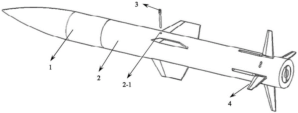
[0023] see Figure 1 to Figure 6 As shown, 1 is the missile head, and 2 is the missile body. On the missile body 2, there is a pin pulling hole 2-1 for inserting the pulling pin 3, and a rotating shaft hole 2-2 for installing the rotating shaft 10. The front end of the missile body 2 has The front end blind hole 2-4 has a middle through hole 2-5 in the middle, and the rear end has a rear end blind hole 2-6. The axis of the pin pulling hole 2-1 passes through the center of mass of the missile, and the purpose of doing this is to minimize the impact on the attitude of the missile when the pin pulling action is performed. The front nut 6 of the push rod is connected with the front end of the push rod 8 by threads, and a large spring 7 is arranged behind the front nut 6 of the push rod. Big spring 7 is enclosed within on the push rod 8, and big spring 7 front ends withst...


PUM


Abstract

The invention discloses a device for a control surface unfolding wind tunnel test of a free flight model, which comprises a flexible head, a flexible body, a folding rudder and an unfolding mechanism, wherein the unfolding mechanism comprises a push rod which is equipped with a round boss on the rear section, a front nut, a rear nut, a big spring and a small spring, a front end blind hole, a rear end blind hole and a middle through hole communicated with the two blind holes are disposed inside the flexible body, an installation groove used to install the folding rudder and a spindle installation hole are disposed in an flexible body wall of the rear end blind hole, the push rod passes through the middle through hole, the big spring is sleeved into the push rod from the front end and installed in the front end blind hole and then limited by the front nut and the bottom wall of the front blind hole, the small spring is sleeved into the push rod from the rear end and fixed on the round boss, a rudder plate of the folding rudder is installed in the installation groove by a spindle, the rear nut is connected on the push rod by threads on the rear side of the folding rudder, a chamfer is disposed on the front end of the rear nut, the top end of the chamber is contacted with a coordination face on the rear end of the folding rudder when the folding rubber is folded, and the flexible head is installed on the front end of the flexible body after installation of the unfolding mechanism. The device is simple in processing and convenient in installation.

Description

Technical field: [0001] The invention relates to the support and release of a wind tunnel test model, in particular to a wind tunnel test device for deploying a rudder surface of a free-flying model, belonging to the field of aerospace engineering. technical background: [0002] One of the main features of future fighter jets is the stealth feature, which requires that the missiles of the aircraft can no longer be hung under the wings as before, but should be hidden inside the fuselage, and the hatch should be opened when it needs to be launched. However, the size of the bomb bay of an aircraft is often limited. How to make better use of the space in the cabin and mount as many missiles as possible has become an important indicator for evaluating the level of combat effectiveness of future fighters. However, in order to make the flight of the missile more flexible and controllable, the rudder surface of the missile is often relatively large, and the rudder surface protruding...

Claims


Application Information

Patent Timeline
IPC IPC(8): G01M9/08
CPCG01M9/08
Inventor 薛飞杨益农朱剑
Owner CHINA ACAD OF AEROSPACE AERODYNAMICS
Learn More