Device for automatically controlling humidity

A humidity and controller technology, applied in non-electric variable control, humidity control, control/regulation systems, etc., can solve problems such as reducing humidity, and achieve the effect of reducing humidity and monitoring humidity in real time

Inactive Publication Date: 2016-03-23
天津海润恒通高性能计算系统科技有限公司
6 Cites 0 Cited by

AI-Extracted Technical Summary

Problems solved by technology

[0002] Existing equipment for detecting and controlling humidity can only use humidity sensors to monitor environmental humidity parameters. Once the environmental humidity exceeds the preset humidity standard value inside the equipment, it can o...

Abstract

The invention provides a device for automatic controlling humidity. The device includes a humidity sensor unit, a control unit, an external network signal receiving unit, an information sending unit and an actuator unit; the output end of the humidity sensor unit is electrically connected with the signal input end of the controller unit; the control output end of the controller unit is electrically with the information sending unit and the actuator unit respectively; and the controller unit is in communication connection with the external network signal receiving unit. With the device of the invention adopted, humidity can be monitored in real time, and once the humidity exceeds standards, an action for reducing the humidity can be automatically carried out.

Application Domain

Humidity control

Technology Topic

Image

  • Device for automatically controlling humidity
  • Device for automatically controlling humidity

Examples

  • Experimental program(1)

Example Embodiment

[0017] It should be noted that the embodiments of the present invention and the features in the embodiments can be combined with each other if there is no conflict.
[0018] Hereinafter, the present invention will be described in detail with reference to the drawings and in conjunction with the embodiments.
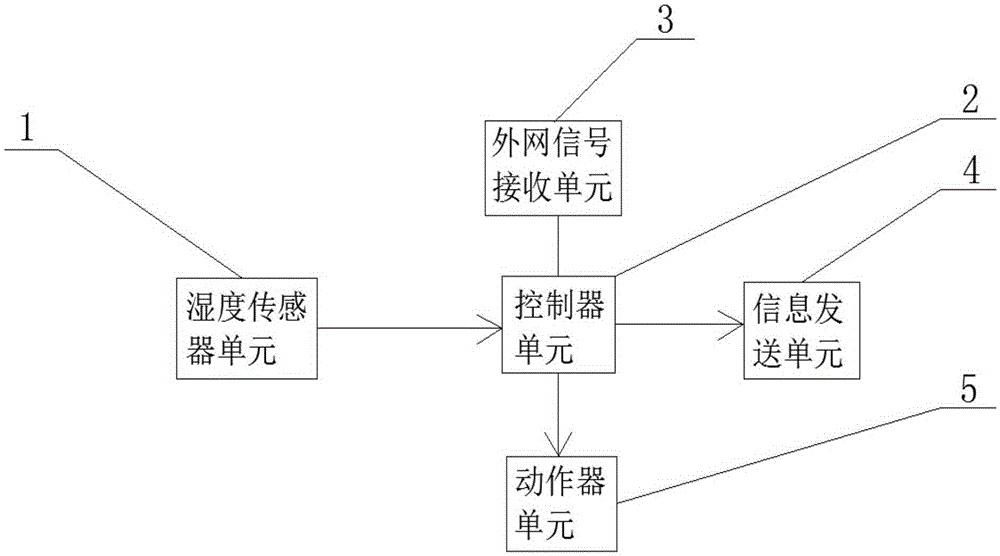
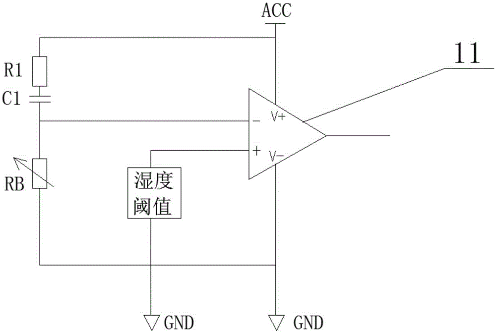
[0019] Such as figure 1 , 2 As shown, the present invention provides a device for automatically controlling humidity, including a humidity sensor unit 1, a controller unit 2, an external network signal receiving unit 3, an information sending unit 4, and an actuator unit 5. The output of the humidity sensor unit 1 The terminal is electrically connected to the signal input terminal of the controller unit 2, and the control output terminal of the controller unit 2 is electrically connected to the information sending unit 4 and the actuator unit 5, respectively. The controller unit 2 also It is in communication connection with the external network signal receiving unit 3.
[0020] The humidity sensor unit 1 includes a humidity sensitive resistor RB, a first resistor R1, a first capacitor C1 and an operational amplifier 11. The first resistor R1, the first capacitor C1 and the humidity sensitive resistor RB are connected in series in sequence Between the AC power supply and the ground, the inverting input terminal of the operational amplifier 11 is electrically connected to the input terminal of the humidity sensitive resistor RB, the non-inverting input terminal of the operational amplifier 11 is provided with a humidity threshold, and the operational amplifier 11 The output terminal of is electrically connected to the signal input terminal of the controller unit 2.
[0021] The controller unit 2 is a single-chip microcomputer.
[0022] The external network signal receiving unit 3 is a SIM card signal connection circuit.
[0023] The external network signal receiving unit 3 is a WIFI signal receiving circuit.
[0024] The working process of this example: the humidity sensor unit 1 monitors the voltage level of humidity in real time, and compares the voltage level with the humidity threshold set by the operational amplifier 11. If the real-time voltage level is higher than the humidity threshold , The output terminal of the operational amplifier 11 will output a high-voltage signal to the controller unit 2, and the control output terminal of the controller unit 2 controls the actuator unit 5 to take corresponding actions to reduce humidity, and also controls the information sending unit 4 to receive signals through the external network Unit 3 sends a prompt message to the user; if the real-time voltage level is lower than the humidity threshold, the output terminal of the operational amplifier 11 will output a low-voltage signal to the controller unit 2, and the control terminal of the controller unit 2 will not start
[0025] The above descriptions are only preferred embodiments of the present invention and are not intended to limit the present invention. Any modification, equivalent replacement, improvement, etc. made within the spirit and principle of the present invention shall be included in the present invention. Within the scope of protection.

PUM

no PUM

Description & Claims & Application Information

We can also present the details of the Description, Claims and Application information to help users get a comprehensive understanding of the technical details of the patent, such as background art, summary of invention, brief description of drawings, description of embodiments, and other original content. On the other hand, users can also determine the specific scope of protection of the technology through the list of claims; as well as understand the changes in the life cycle of the technology with the presentation of the patent timeline. Login to view more.

Similar technology patents

Mixed mortar mixer for construction site

InactiveCN108189225AReal-time monitoring of humidityHumidity adjustmentMixing operation control apparatusIngredients proportioning apparatusPistonWater pipe
Owner:SHENZHEN SHENGTENG ENTERPRISE MANAGEMENT CO LTD

Structure-improved liquid valve

Owner:安徽中兴流体装备有限责任公司

Intelligent ironwood tray

InactiveCN107226260ANon-slipReal-time monitoring of humidityRigid containersInfrared emitterIronwood
Owner:安徽省祥鸿贸易有限公司

Classification and recommendation of technical efficacy words

  • Reduce humidity
  • Real-time monitoring of humidity

Deodorization dehydrating device for cultivation

InactiveCN101336616AReduce ammonia odorReduce humidityAnimal housingBird housingsWinter seasonLivestock
Owner:马剑英

Mixed mortar mixer for construction site

InactiveCN108189225AReal-time monitoring of humidityHumidity adjustmentMixing operation control apparatusIngredients proportioning apparatusPistonWater pipe
Owner:SHENZHEN SHENGTENG ENTERPRISE MANAGEMENT CO LTD

Structure-improved liquid valve

Owner:安徽中兴流体装备有限责任公司

Intelligent ironwood tray

InactiveCN107226260ANon-slipReal-time monitoring of humidityRigid containersInfrared emitterIronwood
Owner:安徽省祥鸿贸易有限公司
Why Eureka
Try Eureka